A/T Removal (A/T)
A/T Removal
| 1. | Before disconnecting the battery, make sure you have the anti-theft code for the radio (and navigation system), then write down the frequencies for the radio's preset stations, if equipped. |
| 2. | Raise the vehicle, and make sure it is supported securely. |
| 3. | Remove the splash shield. |
| 4. | Remove the drain plug (A), and drain the automatic transmission fluid (ATF).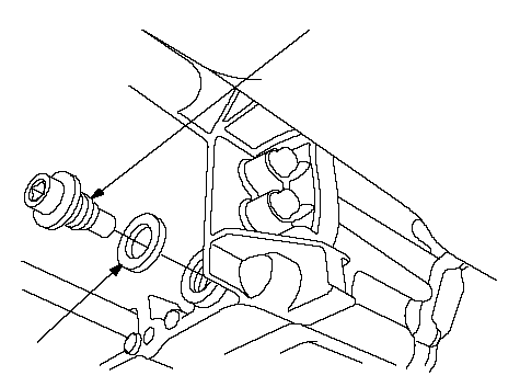 BA BA18 x 1.5 mm 49 N·m (5.0 kgf·m, 36 lbf·ft) |
| 5. | Reinstall the drain plug with a new sealing washer (B). |
| 6. | Disconnect the battery negative terminal, then disconnect the battery positive terminal. |
| 7. | Remove the battery hold-down bracket, then remove the battery cover, battery, and battery tray. |
| 8. | Remove the intake air duct and air cleaner housing. |
| 9. | Loosen the two bolts securing the battery base from under the vehicle, and remove the two bolts securing the battery base in the engine compartment, then remove the battery base. |
| 10. | Disconnect the A/T clutch pressure control solenoid valve A connector, and 2nd clutch transmission fluid pressure switch connector (B), and remove the harness clamps (C) from the clamp brackets (D).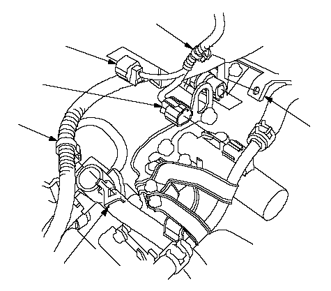 CBDACD CBDACD |
| 11. | Remove the transmission range switch connector (A) from its bracket (B), then disconnect it.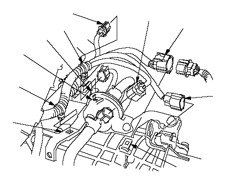 CBDAGFHEHG CBDAGFHEHG |
| 12. | Remove the A/F sensor connector (C) from its bracket (D), then disconnect it. |
| 13. | Disconnect the mainshaft speed sensor connector (E) and countershaft speed sensor connector (F), and remove the harness clamps (G) from the clamp brackets (H). |
| 14. | Disconnect the 3rd clutch transmission fluid pressure switch connector (A), and remove the harness clamp (B) from the clamp bracket (C).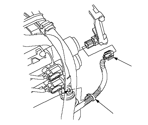 CBA CBA |
| 15. | Disconnect the shift solenoid harness connector (A), A/T clutch pressure control solenoid valve B connector, and solenoid valve C connector, and remove the harness clamp (D) from the clamp bracket (E).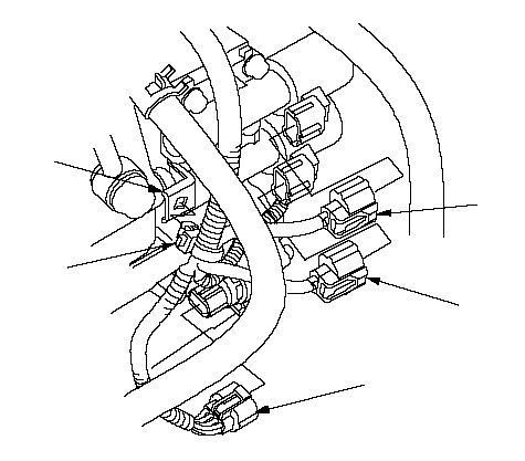 CBDAE CBDAE |
| 16. | Remove the ATF cooler hoses (A) from the ATF cooler lines (B). Turn the ends of the ATF cooler hoses up to prevent ATF from flowing out, then plug the ATF cooler hoses and lines.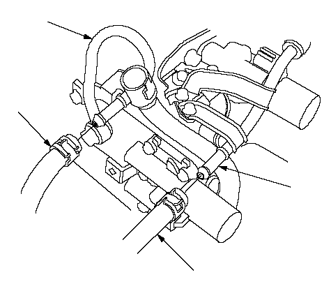 BABA BABA |
| 17. | Check for any signs of leakage at the hose joints. |
| 18. | Remove the ATF cooler hose (A) from the hose clamp (B).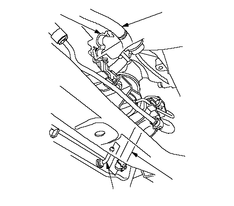 CBDA CBDA |
| 19. | Disconnect the ATF cooler hose (C) from the ATF cooler line (D), then plug the hose end. |
| 20. | Remove the ground cable (A), transmission upper mount bracket plate (B), and transmission upper mount bracket (C).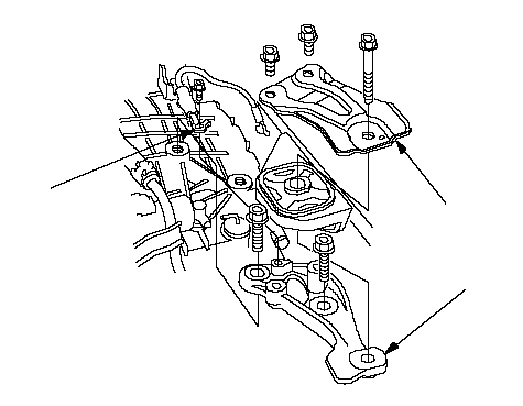 BCA BCA |
| 21. | Attach the hanger plate (A) to the stud nut (B) on the ERG passage with 8×1.25-16 mm bolt (C).Use only the 8×1.25 mm and 16 mm in length of the threads bolt. If you use other than 16 mm threads-length bolt, it may damege the engine cylinder head.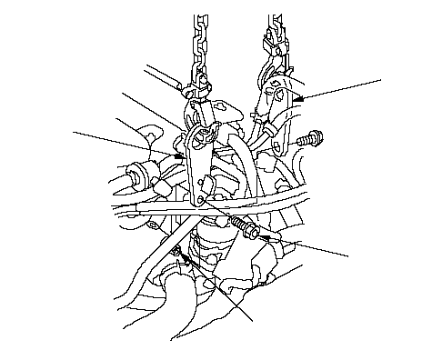 ABCD ABCD |
| 22. | Attach the hanger plate (D) to the threaded hole in the back of the cylinder head. Attach the hoist to the hanger plates, and lift and support the engine.Do not attach the hoist to the engine directly, always use the hanger plates. |
| 23. | Remove the vacuum hose (A) from its clamp (B), then disconnect the hose from the vacuum line (C).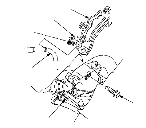 CBDAEF CBDAEF |
| 24. | Remove the front mount stop (D) and clamp bracket (E), and remove the front mount bolt (F). |
| 25. | Insert a 6 mm Allen wrench (A) in the top of the ball joint pin (B), and remove the nuts (C), then separate the stabilizer link (D) from the lower arms (E).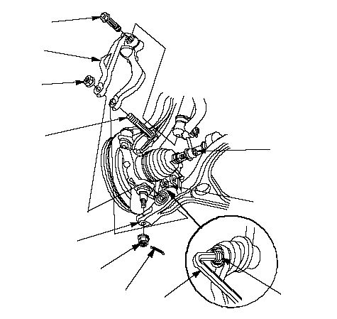 CBDAGFHEJIK CBDAGFHEJIK |
| 26. | Remove the cotter pins (F), castle nuts (G), damper pinch bolt (H), self-locking nut (I), bolt (J), and damper forks (K), then separate the ball joints from the lower arms. |
| 27. | Remove the exhaust pipe A.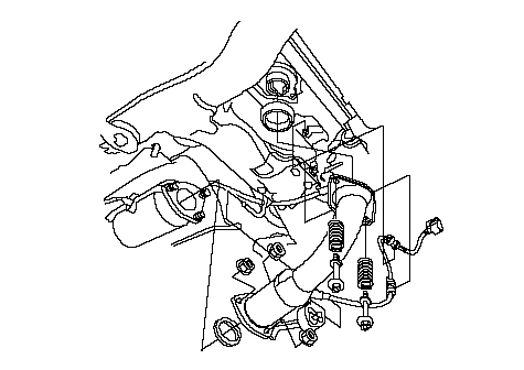 |
| 28. | Remove the steering gearbox heat shield (A). Remove the bolt (B) securing the power steering fluid line bracket (hydraulic P/S model). NOTE: The illustration shows LHD model; RHD model is similar. 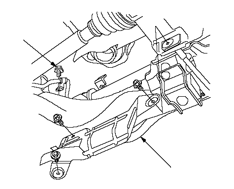 BA BA |
| 29. | Remove the power steering fluid line from its clamps on the front subframe (hydraulic P/S model).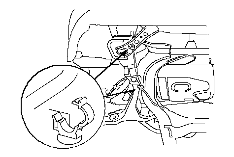 |
| 30. | Remove the engine stiffener (A), and remove the drive plate bolts (B) while rotating the crankshaft pulley.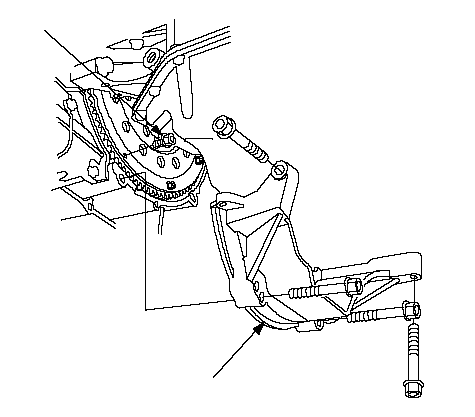 BA BA |
| 31. | Remove the three bolts securing the shift cable holder (A), then remove the shift cable cover (B).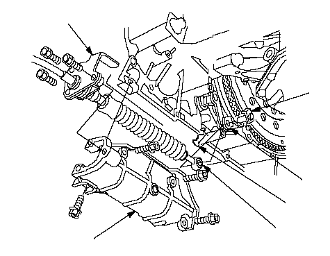 EACFDB EACFDB |
| 32. | Remove the spring clip (C) and control pin (D), then separate the shift cable (E) from the control lever (F). Do not bend the shift cable excessively. |
| 33. | Remove the rear mount stop.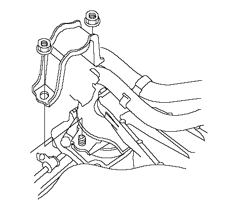 |
| 34. | Remove the power steering fluid line bracket (A) (hydraulic P/S model) or harness clamp bracket (A) (EPS model) from the front subframe. NOTE: The illustration shows LHD model; RHD model is similar. 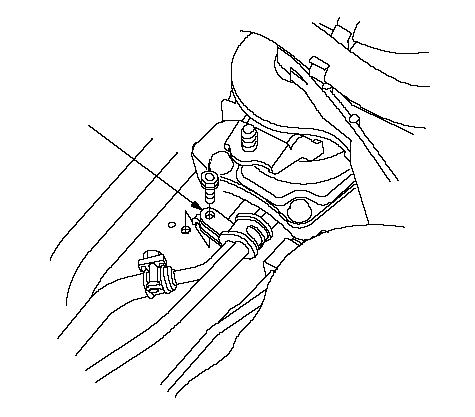 A A |
| 35. | Remove the steering gear box mounting bolts and stiffener. NOTE: The illustration shows LHD model; RHD model is similar. 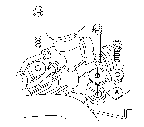 |
| 36. | Remove the steering gearbox mounting bracket bolts. NOTE: The illustration shows LHD model; RHD model is similar. 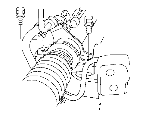 |
| 37. | Remove the rear mount base bracket bolts.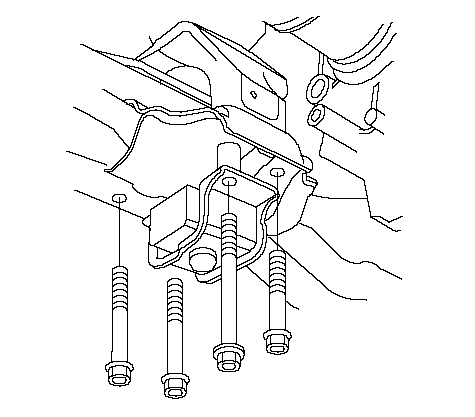 |
| 38. | Remove the transmission lower mounts nuts.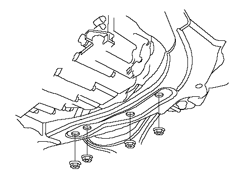 |
| 39. | Remove the both mid-mounts.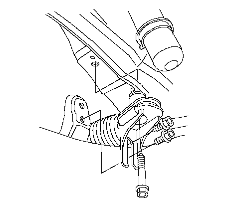 |
| 40. | Make the appropriate reference lines (A) at both ends of the subframe (B) that line up with the edge (C) of the stiffeners (D).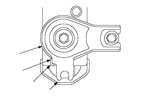 BADC BADC |
| 41. | Support the subframe (A) with a 4×4×40 in. piece of wood (B) and a jack. AB AB |
| 42. | Remove the four bolts securing the stiffeners (A), and four bolts securing the front subframe (B).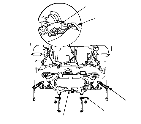 DCABA DCABA |
| 43. | Lower the front subframe by sliding the steering gearbox (C) out to clear the gearbox mounting braket (D) on the subframe. |
| 44. | Hang the steering gearbox to the body with a rope. |
| 45. | Remove the transmission lower mounts.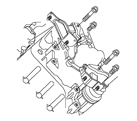 |
| 46. | Pry out the driveshafts from the differential and the intermediate shaft. |
| 47. | Remove the intermediate shaft.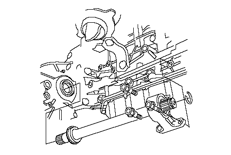 |
| 48. | Coat all precision finished surfaces with clean engine oil, then tie plastic bags over driveshaft ends and intermediate shaft ends. |
| 49. | Remove the rear mount/base bracket (A).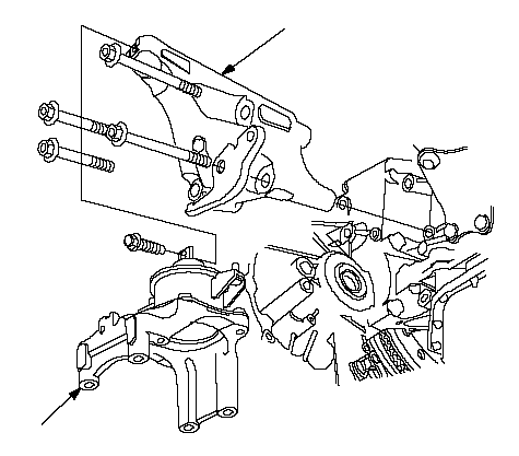 BA BA |
| 50. | Remove the rear mount bracket (B). |
| 51. | Place a jack under the transmission. |
| 52. | Remove the transmission housing mounting bolts.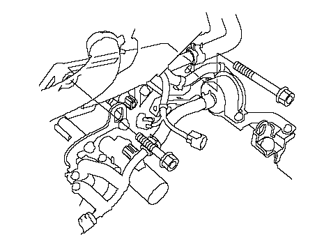 |
| 53. | Remove the front mount bracket.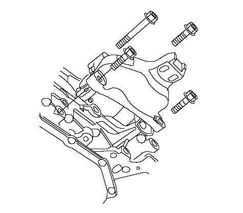 |
| 54. | Remove the transmission housing mounting bolts.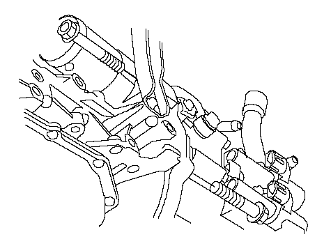 |
| 55. | Remove the transmission housing mounting bolts.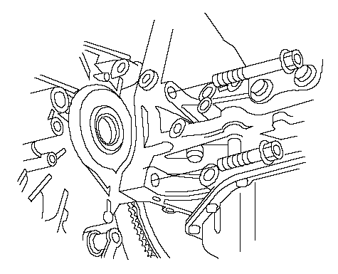 |
| 56. | Slide the transmission away from the engine to remove it from the vehicle. |
| 57. | Remove the torque converter.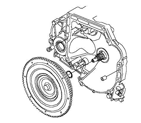 |
| 58. | Inspect the drive plate, and replace it if it's damaged. |
| 59. | Check the transmission lower fornt mount (A) and lower rear mount (B). If the mount rubber (C) is worn or damaged, replace the mount. It is no need to replace the lower rear mount if its sub-mount rubber (D) has raptured or cracks, reuse it.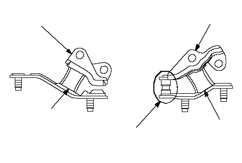 ACDCB ACDCB |