DTC Troubleshooting: 85-61, 85-62
DTC Troubleshooting: 85-61, 85-62
| DTC 85-61: | No Signal from OPDS Unit |
NOTE:
- An incorrect OPDS unit can cause DTC 85-63
- A new (uninitialized) OPDS unit installed with a faulty sensor can also cause DTC 85-71
- If you install a new OPDS unit and a new SRS unit at the same time, initialize the OPDS.
| 1. | Make sure nothing is on the front passenger's seat. |
| 2. | Erase the DTC memory. |
| 3. | Read the DTC. Is DTC 85-61 or 85-62 indicated? YES - Go to 4. NO - Intermittent failure, system is OK at this time. Go to Troubleshooting Intermittent Failures. |
| 4. | Check the connection between the OPDS unit harness 8P connector and the OPDS unit. Is the connection OK? YES - Go to 6. NO - Repair the poor connection and retest. If DTC 85-61 or 85-62 is still present, go to 6. |
| 5. | Erase the DTC. |
| 6. | Read the DTC. Is DTC 85-61 or 85-62 indicated? YES - Go to 7. NO - Intermittent failure, system is OK at this time. Go to Troubleshooting Intermittent Failures. If another DTC is indicated, go to the DTC Troubleshooting Index. |
| 7. | Turn the ignition switch OFF. |
| 8. | Check the No. 10 (7.5A) fuse in the under-dash fuse/relay box. Is the fuse OK? YES - Go to 9. NO - Replace the fuse, then turn the ignition switch ON (II). If the fuse blows again, check for a short in the No. 10 (7.5A) fuse circuit (dashboard wire harness, floor wire harness, or OPDS unit harness).n |
| 9. | Disconnect the OPDS unit harness 8P connector (A) from the OPDS unit.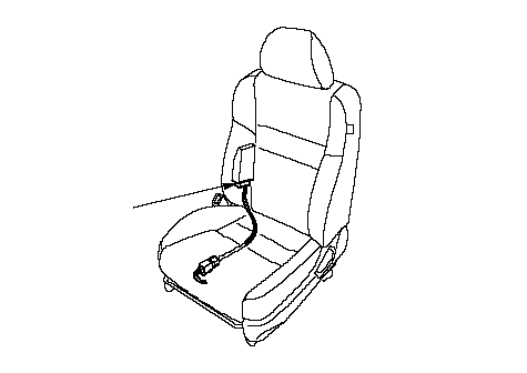 A A |
| 10. | Turn the ignition switch ON (II). |
| 11. | Check for voltage between the No. 4 terminal of the OPDS unit harness 8P connector and body ground. There should battery voltage. 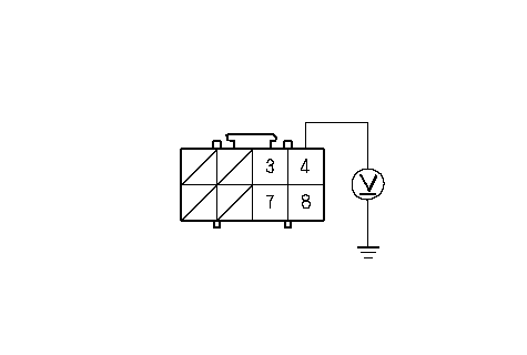 OPDS UNIT HARNESS 8P CONNECTORWire side of female terminalsWHT OPDS UNIT HARNESS 8P CONNECTORWire side of female terminalsWHTIs there battery voltage? YES - Go to 16. NO - Go to 12. |
| 12. | Turn the ignition switch OFF. |
| 13. | Disconnect dashboard wire harness 24P connector (A) from the floor wire harness.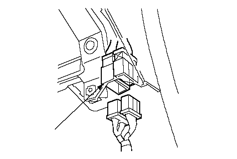 A A |
| 14. | Turn the ignition switch ON (II). |
| 15. | Check for voltage between the No. 8 terminal of dashboard wire harness 24P connector and body ground. There should be battery voltage.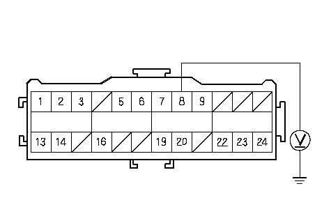 WHTDASHBOARD WIRE HARNESS 24P CONNECTORTerminal side of male terminals WHTDASHBOARD WIRE HARNESS 24P CONNECTORTerminal side of male terminalsIs there battery voltage? YES - Open in the WHT wire of the floor wire harness or OPDS unit harness; replace the faulty harness.n NO - Open in the WHT wire of the dashboard wire harness; replace the dashboard wire harness.n |
| 16. | Turn the ignition switch OFF. |
| 17. | Check resistance between the No. 8 terminal of the OPDS unit harness 8P connector and body ground. There should be 0-1.0 W.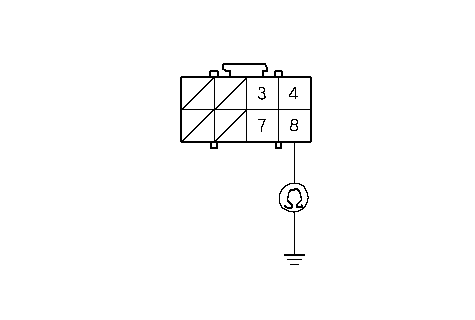 OPDS UNIT HARNESS 8P CONNECTORWire side of female terminalsWHT/BLU OPDS UNIT HARNESS 8P CONNECTORWire side of female terminalsWHT/BLUIs the resistance as specified? YES - Go to 18. NO - Open in the OPDS unit harness or floor wire harness; replace the faulty harness.n |
| 18. | Turn the ignition switch OFF. Disconnect the battery negative cable, and wait for 3 minutes. |
| 19. | Disconnect both seat belt tensioner 4P connectors. |
| 20. | Disconnect SRS unit connector B (28P) from the SRS unit. |
| 21. | Check resistance between the No. 27 terminal of SRS unit connector B (28P) and body ground. There should be an open circuit, or at least 1 MW.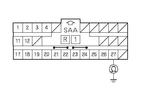 SRS UNIT CONNECTOR B (28P)Wire side of female terminals GRN/ORN SRS UNIT CONNECTOR B (28P)Wire side of female terminals GRN/ORNIs the resistance as specified? YES - Go to 22. NO - Go to 25. |
| 22. | Check resistance between the No. 27 terminal of SRS unit connector B (28P) and the No. 7 terminal of the OPDS unit harness 8P connector. There should be 0-1.0 W.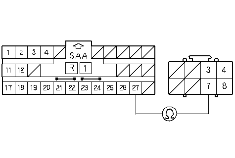 SRS UNIT CONNECTOR B (28P)Wire side of female terminals GRN/ORNOPDS UNIT HARNESS SRS UNIT CONNECTOR B (28P)Wire side of female terminals GRN/ORNOPDS UNIT HARNESS8P CONNECTORORN Is the resistance as specified? YES - Faulty OPDS unit or SRS unit; replace the OPDS unit. If the problem is still present, replace the SRS unit.n NO - Go to 23. |
| 23. | Disconnect the floor wire harness 4P connector (A) from the OPDS unit harness.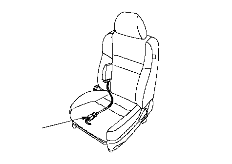 A A |
| 24. | Check resistance between the No. 27 terminal of SRS unit connector B (28P) and the No. 4 terminal of floor wire harness 4P connector. There should be 0-1.0 W.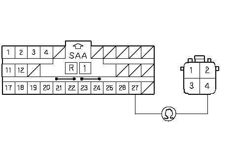 SRS UNIT CONNECTOR B (28P)Wire side of female terminals GRN/ORNFLOOR WIRE HARNESS SRS UNIT CONNECTOR B (28P)Wire side of female terminals GRN/ORNFLOOR WIRE HARNESS4P CONNECTOR Is the resistance as specified? YES - Open in the OPDS unit harness; replace the OPDS unit harness.n NO - Open in the GRN/ORN wire of the floor wire harness; replace the floor wire harness.n |
| 25. | Disconnect floor wire harness 4P connector (A) from the OPDS unit harness.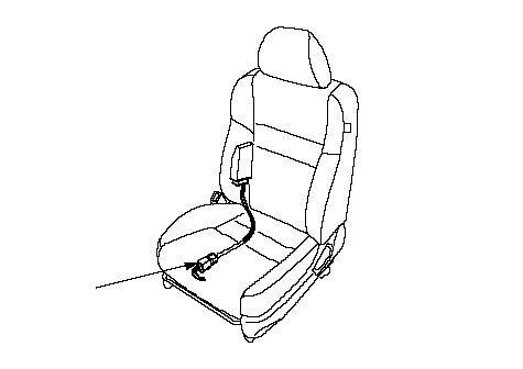 A A |
| 26. | Check resistance between the No. 27 terminal of SRS unit connector B (28P) and body ground. There should be an open circuit, or at least 1 MW.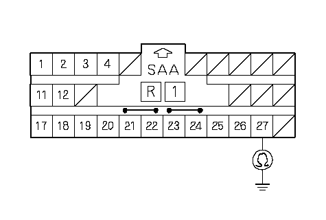 SRS UNIT CONNECTOR B (28P)Wire side of female terminals GRN/ORN SRS UNIT CONNECTOR B (28P)Wire side of female terminals GRN/ORNIs the resistance as specified? YES - Short to ground in the OPDS unit harness; replace the OPDS unit harness.n NO - Short to ground in the floor wire harness; replace the floor wire harness.n |