Honda Accord ESM 2003 · Service Manual Service Manual 2003

Keyless Entry/Security Alarm System Control Unit Input Test

Keyless Entry/Security Alarm System Control Unit Input Test

1.Before testing the keyless entry/security control functions, troubleshoot the multiplex integrated control system..

Multiplex Integrated Control Unit


2.Remove the left kick panel (LHD type) or right kick panel (RHD type).

3.Disconnect the under-dash fuse/relay box connectors.

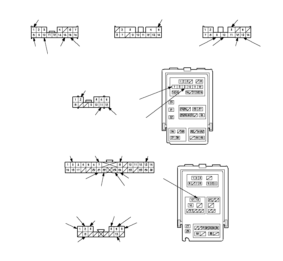
NOTE: All connectors are wire side of female terminals.

SEA3E00J46643441951FCAD01UNDER-DASH FUSE/RELAY BOX
CONNECTOR E (16P)
UNDER-DASH FUSE/RELAY BOX
CONNECTOR H (14P)
UNDER-DASH FUSE/RELAY BOX
CONNECTOR K (12P)
UNDER-DASH FUSE/RELAY BOX
CONNECTOR P (30P)
UNDER-DASH FUSE/RELAY BOX CONNECTOR N (45P)UNDER-DASH FUSE/RELAY BOX
CONNECTOR Q (14P)
YELGRN/YELUNDER-DASH FUSE/RELAY BOX
CONNECTOR F (14P)
GRNYEL/BLKYEL/GRNYEL/BLKGRN/WHTLT GRN/REDYELYELYEL/BLKYEL/BLKBRN*1PNK*1WHT/GRN*2BLU/BLK*2BLKLT GRN/RED*4YELRED/WHT*2LT GRN*2RED/WHT*1WHT/GRN*1UNDER-DASH FUSE/RELAY BOX
CONNECTOR Q (14P)
YEL*3BRN*2RED*1GRY*1WHT*1RED*2ORN*2RED/BLU*2*1: LHD type*2: RHD type*3: With ultrasonicLT GRN*1LT GRN/RED*4GRY/RED*4*4: KE model

4.Inspect the connector and socket terminals to be sure they are all making good contact.

  • If the terminals are bent, loose or corroded, repair them as necessary, and recheck the system.
  • If the terminals look OK, go to 5.

5.With the connectors still disconnected, make these input tests at the connectors.

  • If any test indicates a problem, find and correct the cause, then recheck the system.
  • If the input tests prove OK, go to 6.

Cavity Wire Test condition Test: Desired result Possible cause if result is not obtained 
H9 BLK Under all conditions Check for continuity to ground:
There should be continuity. 
  • Poor ground (G601)
  • An open in the wire
 
F5 YEL/GRN Connect the F5 terminal to the battery positive terminal momentarily. Check trunk opener operation:
Trunk lid should open. 
  • Poor ground (G701)
  • Faulty trunk opener solenoid
  • An open in the wire
 
K11 YEL Connect the battery positive terminal to K12 (K11) terminal, and K11 (K12) terminal to H9 terminal. Check actuator operation:
The driver's door lock actuator should lock (unlock). 
  • Faulty driver's door lock actuator
  • An open in the wire
 
K12 YEL/BLK 
N7 YEL/BLK Connect the battery positive terminal to N7 (N9) terminal, and N9 (N7) terminal to H9 terminal. Check actuator operation:
The front passenger's door lock actuator should lock (unlock). 
  • Faulty front passenger's door lock actuator
  • An open in the wire
 
N9 YEL 
  E2*1
  H3*2 
YEL/BLK Connect the battery positive terminal to E2 or H3 (E8 or H10) terminal, and E8 or H10 (E2 or H3) terminal to H9 terminal. Check actuator operation:
The left rear door lock actuator should lock (unlock). 
  • Faulty left rear door lock actuator
  • An open in the wire
 
  E8*1
  H10*2 
YEL 
  H3*1
  E2*2 
YEL/BLK Connect the battery positive terminal to H3 or E2 (H10 or E8) terminal, and H10 or E8 (H3 orE2) terminal to H9 terminal. Check actuator operation:
The right rear door lock actuator should lock (unlock). 
  • Faulty right rear door lock actuator
  • An open in the wire
 
  H10*1
  E8*2 
YEL 
  P23*1
  P22*2 
WHT/GRN Under all conditions Check for continuity to ground:
There should be continuity. 
  • Faulty hazard warning light relay
  • An open in the wire
 
  K2*3 LT GRN/RED Under all conditions Check for continuity between the K2 terminal and No. 1 terminal of the driver's actuator.
There should be continuity. 
  • An open in the wire
 
  E10*3 LT GRN/RED Under all conditions Check for continuity between the E10 terminal and No. 1 terminal of the right rear actuator.
There should be continuity. 
  • An open in the wire
 
  X13*3 GRY/RED Under all conditions Check for continuity between the X13 terminal and No. 6 terminal of the front passenger's or left rear actuator.
There should be continuity. 
  • An open in the wire
 

*1: LHD type 
*2: RHD type 
*3: With super locking 

6.Reconnect all connectors to the under-dash fuse/relay box, and make these input tests at the appropriate connectors on the under-dash fuse/relay box.

  • If any test indicates a problem, find and correct the cause, then recheck the system.
  • If all the input tests prove OK, go to 7.

Cavity Wire Test condition Test: Desired result Possible cause if result is not obtained 
  Q8*1
  Q13*2 
BRN Front passenger's door lock knob switch unlocked Check for voltage to ground:
There should be 1 V or less. 
  • Poor ground (G503)
  • Faulty front passenger's  door lock knob switch
  • An open in the wire
 
Front passenger's door lock knob switch locked Check for voltage to ground:
There should be 5 V or more. 
  • Faulty front passenger's door lock knob switch
  • Short to ground
 
  Q2*1
  Q5*2 
GRY*1
·
ORN*2 
Left rear door lock knob switch unlocked Check for voltage to ground:
There should be 1 V or less. 
  • Poor ground (G501, G601)
  • Faulty left rear door lock knob switch
  • An open in the wire
 
Left rear door lock knob switch locked Check for voltage to ground:
There should be 5 V or more. 
  • Faulty left rear door lock knob switch
  • Short to ground
 
  Q3*1
  Q4*2 
WHT*1
·
RED*2 
Right rear door lock knob switch unlocked Check for voltage to ground:
There should be 1 V or less. 
  • Poor ground (G602)
  • Faulty right rear door lock knob switch
  • An open in the wire
 
Right rear door lock knob switch locked Check for voltage to ground:
There should be 5 V or more. 
  • Faulty right rear door lock knob switch
  • Short to ground
 
  Q8*3 YEL Under all conditions Check for continuity between the Q8 terminal and No. 2 terminal of the alarm control siren.
There should be continuity. 
  • An open in the wire
 

*1: LHD type 
*2: RHD type 
*3: With super locking 

Cavity Wire Test condition Test: Desired result Possible cause if result is not obtained 
  Q1*1
  Q6*2 
RED*1
·
RED/BLU*2 
Under all conditions Check for continuity to ground:
There should be continuity. 
  • Poor ground (G504)
  • Faulty connections at the audio unit
  • Faulty audio unit
  • An open in the wire
 
  P13*1
  P2*2 
RED/WHT Ignition key inserted into the ignition switch. Check for voltage to ground:
There should be 1 V or less. 
  • Poor ground (G501, G601)
  • Faulty  ignition key switch
  • An open in the wire
 
Ignition key removed from the ignition switch. Check for voltage to ground:
There should be 5 V or more. 
  • Faulty ignition key switch
  • Short to ground
 
E15 GRN Driver's door open Check for voltage to ground:
There should be 1 V or less. 
  • Faulty driver's door switch
  • An open in the wire
 
Driver's door closed Check for voltage to ground:
There should be 5 V or more. 
  • Faulty driver's door switch
  • Short to ground
 
H12 LT GRN/RED Front passenger's door open Check for voltage to ground:
There should be 1 V or less. 
  • Faulty front passenger's door switch
  • An open in the wire
 
Front passenger's door closed Check for voltage to ground:
There should be 5 V or more. 
  • Faulty front passenger's door switch
  • Short to ground
 
  E14*1
  H13*2 
GRN/YEL*1
GRN/WHT*2 
Left rear door open Check for voltage to ground:
There should be 1 V or less. 
  • Faulty left rear door switch
  • An open in the wire
 
Left rear door closed Check for voltage to ground:
There should be 5 V or more. 
  • Faulty left rear door switch
  • Short to ground
 
  H13*1
  E14*2 
GRN/WHT*1
GRN/YEL*2 
Right rear door open Check for voltage to ground:
There should be 1 V or less. 
  • Faulty right rear door switch
  • An open in the wire
 
Right rear door closed Check for voltage to ground:
There should be 5 V or more. 
  • Faulty right rear door switch
  • Short to ground
 
  P24*1
  P21*2 
BLU/BLK Trunk lid open Check for voltage to ground:
There should be 1 V or less. 
  • Poor ground (G701)
  • Faulty  trunk latch switch
  • An open in the wire
 
Trunk lid closed Check for voltage to ground:
There should be 5 V or more. 
  • Faulty trunk latch switch
  • Short to ground
 
  P8*1
  P7*2 
LT GRN Trunk opener switch pushed Check for voltage to ground:
There should be 1 V or less. 
  • Poor ground (G701)
  • Faulty trunk open switch
  • An open in the wire
 
Trunk opener switch released Check for voltage to ground:
There should be 5 V or more. 
  • Faulty trunk open switch
  • Short to ground
 

*1: LHD type 
*2: RHD type 

Door Multiplex Control Unit


7.Remove the driver's power window switch panel.

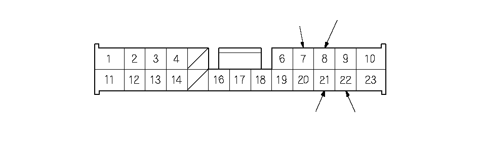
8.Disconnect the 23P connector from the power window master switch.

SDA3A00J46643441951FCAD04WHTWHT/BLKWire side of female terminalsWHT/REDYEL/RED

9.Inspect the connector and socket terminals to be sure they are all making good contact.

  • If the terminals are bent, loose or correded, repair them as nesessary, and receck the system.
  • If the terminals look OK, go to 10.

10.Reconnect the connector to the door multiplex control unit, and make these input tests at the connectors.

  • If any test indicates a problem, find and correct the cause, then recheck the system.
  • If all the input tests prove OK, go to 11.

Cavity Wire Test condition Test: Desired result Possible cause if result is not obtained 
WHT/BLK Driver's door lock knob switch unlocked Check for voltage to ground:
There should be 1 V or less. 
  • Poor ground (G501)
  • Faulty driver's  door lock knob switch
  • An open in the wire
 
Driver's door lock knob switch locked Check for voltage to ground:
There should be 5 V or more. 
  • Faulty driver's door lock knob switch
  • Short to ground
 
22 YEL/RED Driver's door lock knob switch locked Check for voltage to ground:
There should be 1 V or less. 
  • Poor ground (G501)
  • Faulty driver's door lock knob switch
  • An open in the wire
 
Driver's door lock knob switch unlocked Check for voltage to ground:
There should be 5 V or more. 
  • Faulty driver's door lock knob switch
  • Short to ground
 
21 WHT Driver's door key cylinder switch in UNLOCK Check for voltage to ground:
There should be 1 V or less. 
  • Faulty driver's  door key cylinder switch
  • Poor ground (G501)
  • An open in the wire
  • Short to ground
 
Driver's door key cylinder switch in neutral Check for voltage to ground:
There should be 5 V or more. 
Driver's door key cylinder switch in LOCK Check for voltage to ground:
There should be 5 V or more. 
WHT/RED Driver's door key cylinder switch in LOCK Check for voltage to ground:
There should be 1 V or less. 
  • Faulty driver's door key cylinder switch
  • Poor ground (G501)
  • An open in the wire
  • Short to ground
 
Driver's door key cylinder switch in neutral Check for voltage to ground:
There should be 5 V or more. 
Driver's door key cylinder switch in UNLOCK Check for voltage to ground:
There should be 5 V or more. 


11.If all the input tests prove OK, and no DTCs were found during MICS troubleshooting (B-CAN system diagnosis test mode A), go to the B-CAN system input and output index. If multiple failures are found on more than one control unit, replace the under-dash fuse/relay box (includes the MICU). If input failures are related to a particular control unit, replace that control unit.