Audio-HVAC-Display Module Removal/Installation
Audio-HVAC-Display Module Removal/Installation
SRS components are located in this area. Review the SRS component locations, and the precautions and procedures in the SRS section before performing repairs or service.NOTE:
- Put on gloves to protect your hands.
- Take care not to scratch the dashboard and related parts.
- Lay a workshop towel under the parts when working on them to protect the face panel from scratches or other damage.
- Do not work in a dusty or dirty place.
- Discharge static electricity from your body before and during the work.
- Do not touch the circuit board with your bare hands.
- Do not work with dirty hands.
- Be careful not to fold the flat plate cable.
- Do not touch the terminal connector of the flat plate cable with your bare hands. (If you have touched it, wipe it off thoroughly.)
| 1. | Make sure you have the anti-theft codes for the radio and navigation system, then write down the frequencies for the radio's preset buttons. |
| 2. | Remove the upper panel. |
| 3. | Remove the screws and bolts, disconnect the audio-HVAC-display module connectors (A) and the antenna lead (B), then remove the audio-HVAC-display module (C). 6 CD type: 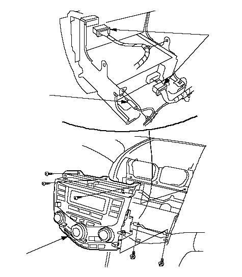 CBA CBA1 CD type: 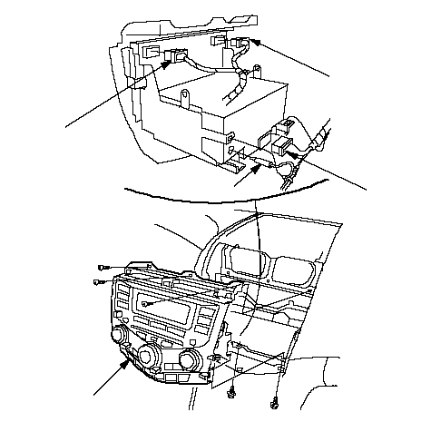 CBAAA CBAAANavigation type: 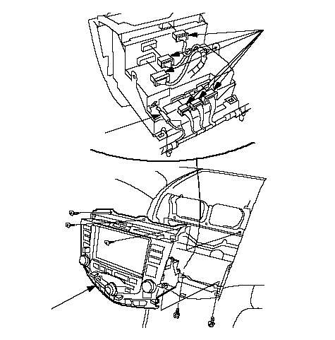 ABC ABC |
| 4. | Remove the mounting screws and the audio unit (A) from the radio brackets (B). 6 CD type: 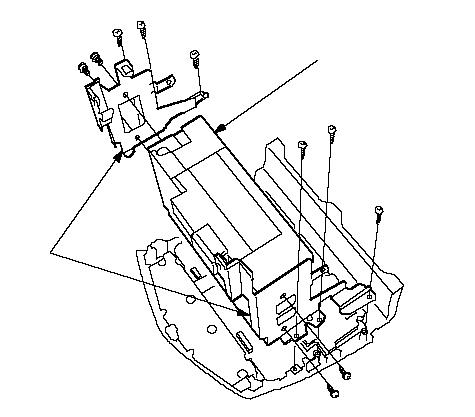 AB AB1 CD type: 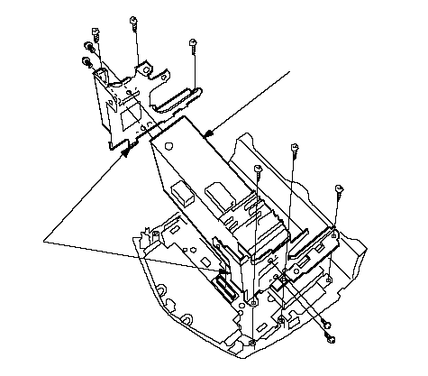 AB ABNavigation type:  BA BA |
| 5. | Remove the mounting screws and the covers (A), then disconnect the connectors (B) (Navigation system) from the printed circuit board (C). 6 CD type: 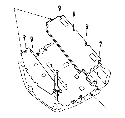 AC AC1 CD type: 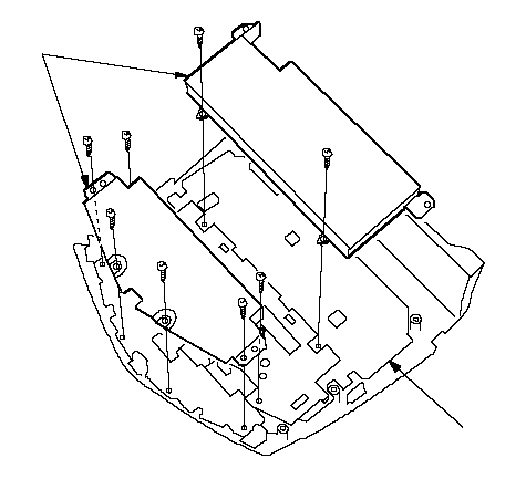 AC ACNavigation type: 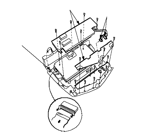 BAC BAC |
| 6. | With navigation system: Remove the mounting screws and display unit (A) from the printed circuit board (B).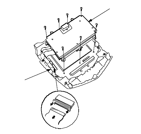 BA BA |
| 7. | Remove the mounting screws and control knobs (A), then remove the printed circuit board (B). 6 CD type: 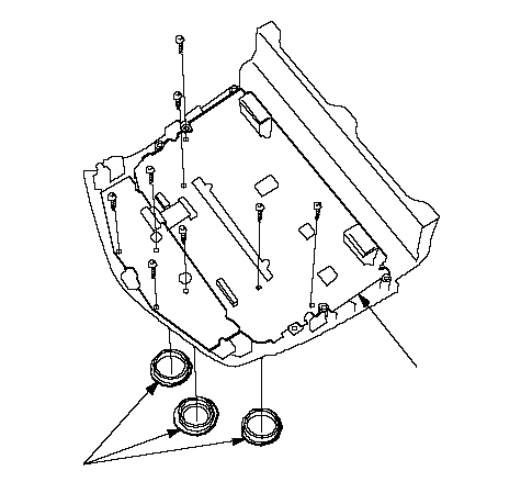 AB AB1 CD type: 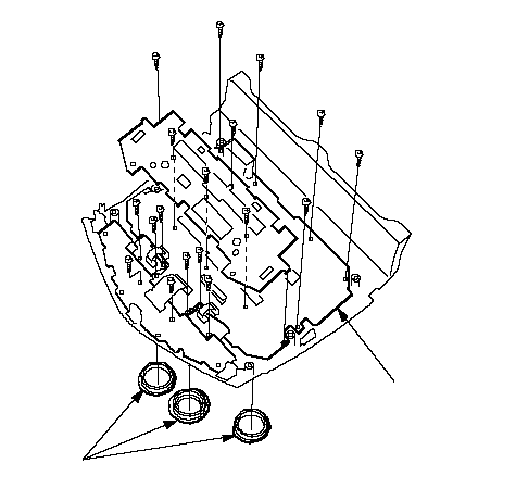 AB ABNavigation type: 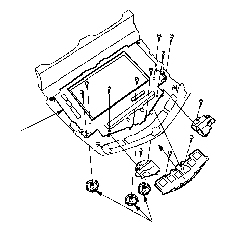 AB AB |
| 8. | Install the audio unit and printed circuit board in the reverse order of removal. |
| 9. | Install the audio-HVAC-display module and note these items:
|