DTC P0717 Input Speed Sensor Circuit No Signal |
| DTC No. | DTC Detection Condition | Trouble Area |
| P0717 |
|
|
| Item | Measurement Item/ Range (Display) | Normal Condition | Diagnostic Note |
| SPD (NT) | Input turbine speed/ display: 50 r/min |
| - |
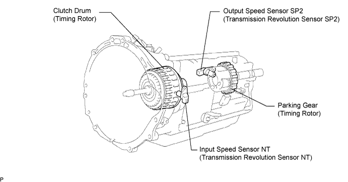
| 1.INSPECT SPEED SENSOR INSTALLATION |
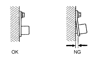 |
Check the speed sensor (NT) installation.
|
| ||||
| OK | |
| 2.INSPECT INPUT SPEED SENSOR (NT) |
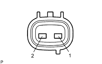 |
Disconnect the T6 sensor connector from the transmission.
Measure the resistance of the sensor.
| Tester Connection | Condition | Specified Condition |
| 1 - 2 | 20°C (68°F) | 560 to 680 Ω |
 |
| Item | Content |
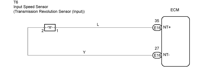
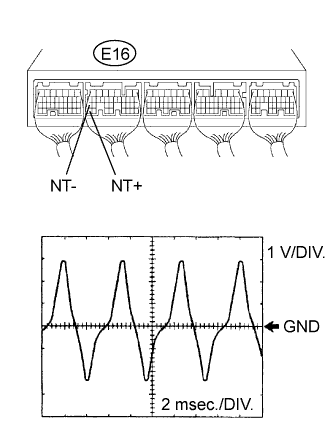
| Tester Connection | E16-35 (NT+) - E16-27 (NT-) |
| Tool Setting | 1 V/DIV., 2 msec./DIV. |
| Condition | Engine idle speed (shift lever on P or N) |
|
| ||||
| OK | |
| 3.CHECK WIRE HARNESS (INPUT SPEED SENSOR - ECM) |
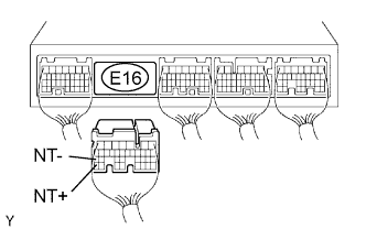 |
Disconnect the E16 ECM connector.
Measure the resistance of the wire harness side connector.
| Tester Connection | Condition | Specified Condition |
| E16-35 (NT+) - E16-27 (NT-) | 20°C (68°F) | 560 to 680 Ω |
| E16-35 (NT+) - Body ground | 20°C (68°F) | 10 kΩ or higher |
| E16-27 (NT-) - Body ground | 20°C (68°F) | 10 kΩ or higher |
|
| ||||
| OK | ||
| ||
