ELECTRONIC CONTROLLED AUTOMATIC TRANSMISSION SYSTEM > TCM Power Source Circuit |
| 1.CHECK TCM (IG2 VOLTAGE) |
 |
Turn the ignition switch ON.
Measure the voltage of the TCM connectors.
| Tester Connection | Specified Condition |
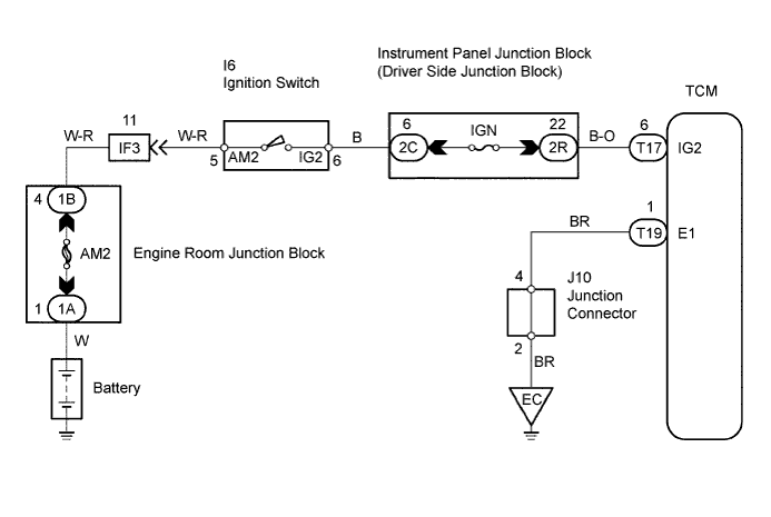
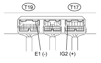
| T17-6 (IG2) - T19-1 (E1) | 9 to 14 V |
|
| ||||
| NG | |
| 2.CHECK WIRE HARNESS (TCM - BODY GROUND) |
 |
Disconnect the T19 TCM connector.
Measure the resistance of the wire harness side connector.
| Tester Connection | Specified Condition |
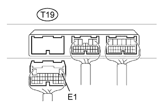
| T19-1 (E1)- Body ground | Below 1 Ω |
|
| ||||
| OK | |
| 3.INSPECT FUSE (IGN) |
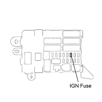 |
Remove the IGN fuse from the instrument panel junction block.
Measure the resistance of the fuse.
|
| ||||
| OK | |
| 4.INSPECT IGNITION SWITCH |
 |
Disconnect the I6 ignition switch connector.
Measure the resistance of the ignition switch.
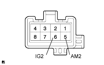
| Tester Connection | Switch Condition | Specified Condition |
| 5 (AM2) - 6 (IG2) | LOCK | 10 kΩ or higher |
| 5 (AM2) - 6 (IG2) | ON | Below 1 Ω |
|
| ||||
| OK | ||
| ||
