ELECTRONIC CONTROLLED AUTOMATIC TRANSMISSION SYSTEM > A/T P Indicator Circuit |
| 1.INSPECT PARK/NEUTRAL POSITION SWITCH |
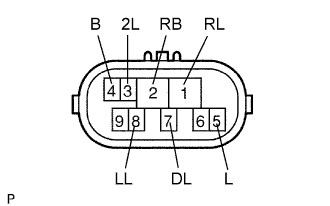 |
Disconnect the N1 PNP switch connector.
Measure the resistance of the PNP switch when the shift lever is moved to each position.
| Tester Connection | Shift Lever Position | Specified Condition |
| 4 (B) - 5 (L) | P or N | Below 1 Ω |
| 4 (B) - 5 (L) | Not on P or N | 10 kΩ or higher |
| 1 (RL) - 2 (RB) | R | Below 1 Ω |
| 1 (RL) - 2 (RB) | Not on R | 10 kΩ or higher |
| 2 (RB) - 7 (DL) | D | Below 1 Ω |
| 2 (RB) - 7 (DL) | Not on D | 10 kΩ or higher |
| 2 (RB) - 3 (2L) | 2 | Below 1 Ω |
| 2 (RB) - 3 (2L) | Not on 2 | 10 kΩ or higher |
| 2 (RB) - 8 (LL) | L | Below 1 Ω |
| 2 (RB) - 8 (LL) | Not on L | 10 kΩ or higher |
|
| ||||
| OK | |
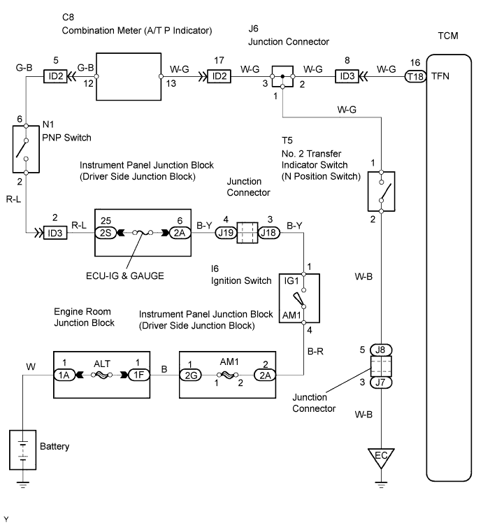
| 2.INSPECT NO. 2 TRANSFER INDICATOR SWITCH (TRANSFER NEUTRAL POSITION SWITCH) |
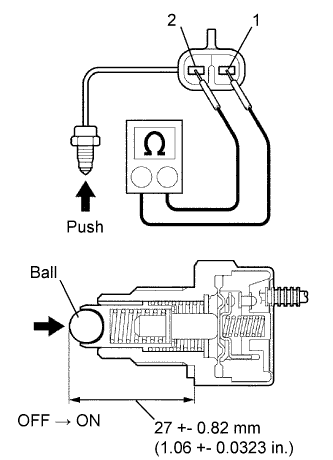 |
Remove the transfer indicator switch.
Measure the resistance of the switch when pushing the ball at the tip of the switch.
| Tester Connection | Switch Condition | Specified Condition |
| 1 - 2 | Not pushed | 10 kΩ or higher |
| 1 - 2 | Pushed | Below 1 Ω |
|
| ||||
| OK | |
| 3.INSPECT COMBINATION METER |
Check the A/T P indicator light.
Disconnect the T5 transfer indicator switch connector.
Turn the ignition switch ON.
Connect the T5-1 terminal of the wire harness side connector to the body ground, and then check the A/T P indicator light.
|
| ||||
| OK | ||
| ||
