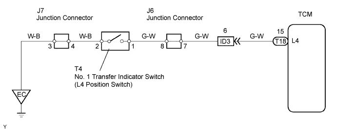
ELECTRONIC CONTROLLED AUTOMATIC TRANSMISSION SYSTEM > L4 Position Switch Circuit |
| 1.INSPECT NO. 1 TRANSFER INDICATOR SWITCH (L4 POSITION SWITCH) |
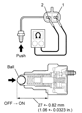 |
Remove the transfer indicator switch.
Measure the resistance of the switch when pushing the ball at the tip of the switch.
| Tester Connection | Switch Condition | Specified Condition |
| 1 - 2 | Not pushed | 10 kΩ or higher |
| 1 - 2 | Pushed | Below 1 Ω |
|
| ||||
| OK | |
| 2.CHECK WIRE HARNESS (NO. 1 TRANSFER INDICATOR SWITCH - TCM AND BODY GROUND) |
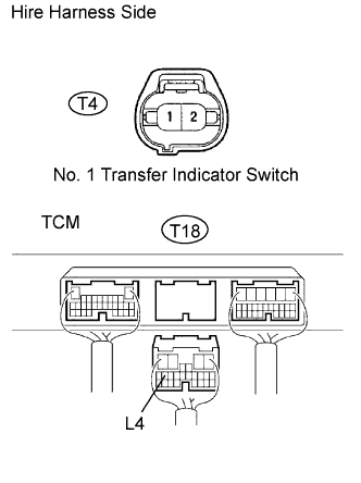 |
Disconnect the T4 indicator switch connector.
Disconnect the T18 TCM connector.
Measure the resistance of the wire harness side connectors.
| Tester Connection | Specified Condition |
| T18-15 (L4) - T4-1 (L4) | Below 1 Ω |
| T4-2 (L4) - Body ground | Below 1 Ω |
| T18-15 (L4) or T4-1 (L4) - Body ground | 10 kΩ or higher |
|
| ||||
| OK | ||
| ||
