OVERDRIVE DIRECT CLUTCH > DISASSEMBLY |
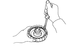
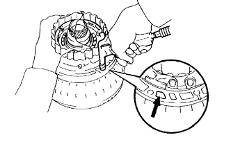
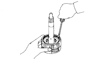
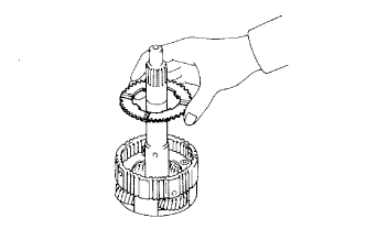
| 1. INSPECT OVERDRIVE ONE-WAY CLUTCH |
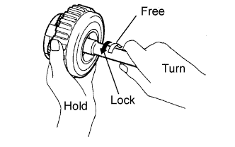 |
Hold the overdrive direct clutch drum, and turn the input shaft.
Check that the input shaft can be turned freely clockwise and locks when turned counterclockwise.
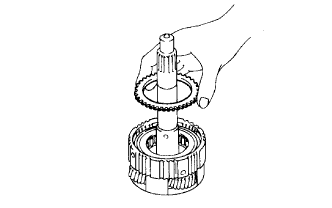
| 2. REMOVE OVERDRIVE DIRECT CLUTCH DRUM |
| 3. INSPECT OVERDRIVE DIRECT CLUTCH DRUM |
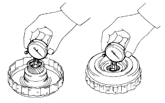 |
Using a dial indicator, measure the inside diameter of the clutch drum bushes.
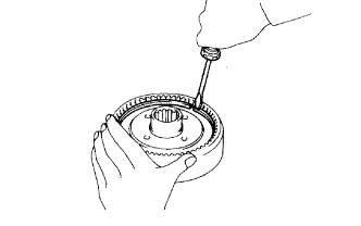
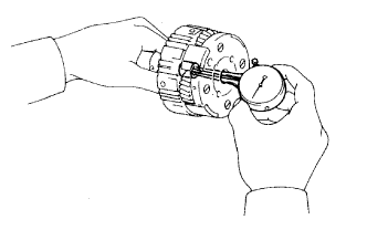
| 4. INSPECT PISTON STROKE OF OVERDRIVE DIRECT CLUTCH |
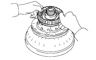 |
Place the oil pump onto the torque converter clutch, and then place the overdrive direct clutch drum assembly onto the oil pump.
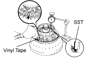 |
Using SST and a dial indicator, measure the overdrive direct clutch piston stroke while applying and releasing compressed air (392 kPa (4.0 kgf/cm2, 57 psi)).
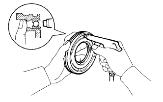
| 5. REMOVE OVERDRIVE DIRECT CLUTCH DISC |
 |
Using a screwdriver, pry out the snap ring from the overdrive direct clutch drum.
Remove the flange, 2 plates and 2 discs.
| 6. INSPECT OVERDRIVE DIRECT CLUTCH DISC |
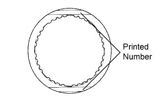 |
Replace all discs if one of the following problems is present: 1) a disc, plate or flange is worn or burnt, 2) the lining of a disc is peeled off or discolored, or 3) grooves or printed numbers have even a little bit of damage.
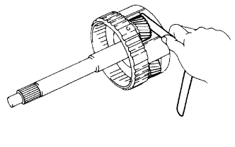
| 7. REMOVE OVERDRIVE DIRECT CLUTCH RETURN SPRING |
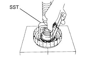 |
Place SST on the spring retainer, and compress the return spring with a press.
Using snap ring pliers, remove the snap ring.
Remove the piston return spring.
| 8. INSPECT OVERDRIVE DIRECT CLUTCH RETURN SPRING |
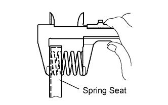 |
Using a vernier caliper, measure the free length of the spring together with the spring seat.
| 9. REMOVE OVERDRIVE DIRECT CLUTCH PISTON |
 |
Place the oil pump onto the torque converter clutch, and then place the overdrive direct clutch onto the oil pump.
Hold the overdrive direct clutch piston by hand, and apply compressed air (392 kPa (4.0 kgf/cm2, 57 psi)) to the oil pump to remove the overdrive direct clutch piston.
Remove the overdrive direct clutch piston.
Remove the 2 O-rings from the piston.
| 10. INSPECT OVERDRIVE DIRECT CLUTCH PISTON |
 |
Check that the check ball is free by shaking the piston.
Check that the valve does not have leaks by applying low-pressure compressed air.
| 11. REMOVE OVERDRIVE PLANETARY RING GEAR FLANGE |
 |
Using a screwdriver, pry out the snap ring.
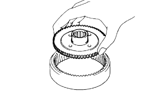 |
Remove the ring gear flange.
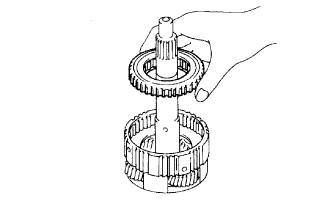
| 12. REMOVE OVERDRIVE RETAINING PLATE |
 |
Using a screwdriver, pry out the snap ring.
 |
Remove the retaining plate.
| 13. REMOVE OVERDRIVE ONE-WAY CLUTCH OUTER RACE |
 |
| 14. REMOVE OVERDRIVE ONE-WAY CLUTCH |
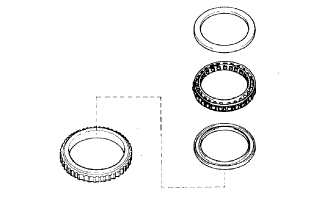 |
Using a screwdriver, pry out the snap ring.
Remove the retaining plate.
| 15. REMOVE NO.3 OVERDRIVE PLANETARY GEAR THRUST WASHER |
 |
| 16. INSPECT OVERDRIVE PLANETARY GEAR |
 |
Using a dial indicator, measure the inside diameter of the planetary gear bush.
 |
Using a feeler gauge, measure the planetary pinion gear thrust clearance.
