STEERING LINKAGE > REASSEMBLY

for Preparation Click here


1. INSTALL STEERING RACK PISTON RING


    C003629E01
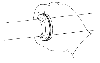
  1. Coat a new O-ring with power steering fluid and install it on the steering rack.

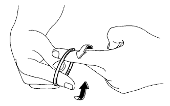
  1. Stretch a new teflon ring with your fingers.

    NOTICE:
    Be careful not to overstretch the teflon ring.

  1. Coat the teflon ring with power steering fluid.


    N000401E01
  1. Install the teflon ring to the steering rack's groove. Grip the ring to press it into the groove.


2. INSTALL POWER STEERING RACK


    W002101E02
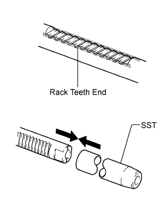
  1. Apply grease to the rack teeth ends.

  1. Install SST to the steering rack.

    SST
    09631-00350  

    HINT:
    If necessary, scrape the burrs off the rack teeth end and burnish.

  1. Coat SST and the power piston oil seal with power steering fluid.

  1. Install the steering rack to the rack housing.

  1. Remove SST.


    F005044E01
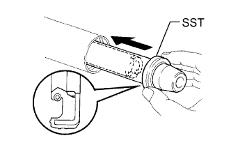
  1. Coat SST with power steering fluid.

    SST
    09631-00350  

  1. Install SST to the steering rack opposite end.

  1. Coat the lip of a new oil seal with power steering fluid. Using SST, install the oil seal to the steering rack.

    NOTICE:
    1. Slide SST and the oil seal straight without tilting them.
    2. Make sure to install the oil seal facing in the correct direction.
    3. Be careful not to damage the lip of the oil seal.

  1. Remove SST.


3. INSTALL CYLINDER END STOPPER


    ZX00351E01
  1. Apply sealant to the stopper.

  1. Using a wooden block and hammer, tap in the stopper until it is tightly installed.

    Sealant:
    Part No. 08833-00080, THREE BOND 1344, LOCTITE 242 or equivalent


    F043535E02
  1. Using SST, tighten the stopper.

    SST
    09631-20120  

    Torque:
    82.5 N*m{ 841 kgf*cm , 61 ft.*lbf }


4. TEST AIR TIGHTNESS


    G038606E01
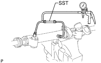
  1. Install SST to the unions of the rack housing.

    SST
    09631-12071   (09633-00010)

  1. Apply 53.33 kPa (400 mmHg, 15.75 in.Hg) of vacuum for about 30 seconds.

  1. Check that there is no change in the vacuum.
    If there is a change in the vacuum, check the installation of the oil seals.


5. INSTALL POWER STEERING CONTROL VALVE


    G035022E01
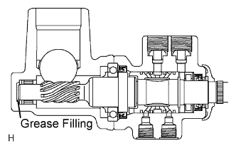
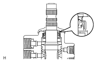
  1. Apply molybdenum disulfide base grease to the needle roller bearing inside the rack housing shown in the illustration.

    Volume of grease applied:
    Approximately 2 g (0.07 oz)


    G100343E01
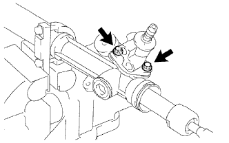
  1. Install the control valve with the 2 bolts.

    Torque:
    18.1 N*m{ 185 kgf*cm , 13 ft.*lbf }


6. INSTALL RACK GUIDE


    G035020E01
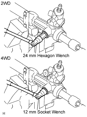
  1. Install the rack guide and spring.

  1. Apply sealant to 2 or 3 threads of the rack guide spring cap.
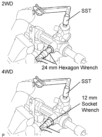
    Sealant:
    Part No. 08833-00080, THREE BOND 1344, LOCTITE 242 or equivalent

  1. 2WD
    Using a 24 mm hexagon wrench, temporarily install the spring cap.

  1. 4WD
    Using a 12 mm socket wrench, temporarily install the spring cap.


7. ADJUST TOTAL PRELOAD


    G035020E02
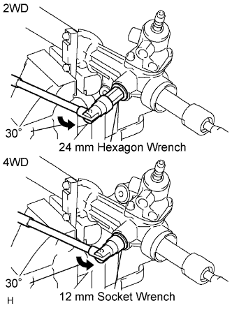
  1. To prevent the steering rack teeth from damaging the lip of the oil seal, temporarily install the RH and LH rack ends.
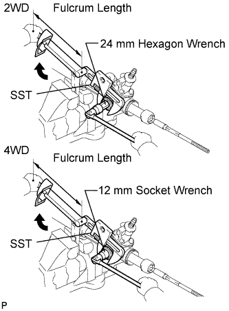
  1. 2WD:
    Using a 24 mm hexagon wrench, tighten the rack guide spring cap.

    Torque:
    25 N*m{ 250 kgf*cm , 18 ft.*lbf }

  1. Loosen the cap 30°.

  1. 4WD:
    Using a 12 mm socket wrench, tighten the rack guide spring cap.

    Torque:
    25 N*m{ 250 kgf*cm , 18 ft.*lbf }

  1. Loosen the cap 30°.


    G100341E01
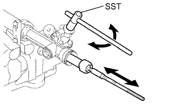
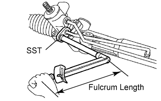
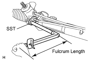
  1. Using SST, turn the control valve shaft right and left 1 or 2 times. The rack end will move in and out.

    SST
    09616-00011  

  1. Using a 24 mm hexagon wrench, loosen the cap until the rack guide spring does not function.


    F051283E01
  1. 2WD:
    Using SST, a torque wrench and 24 mm hexagon wrench, tighten the cap until the preload is within the specification.

    SST
    09616-00011  

    Torque:
    Preload (turning):
    0.8 to 1.6 N*m{ 8.2 to 16.3 kgf*cm , 7.1 to 14.2 in.*lbf }

    NOTICE:
    Perform adjustments in the tightening direction of the spring cap.

  1. 4WD:
    Using SST, a torque wrench and 12 mm socket wrench, tighten the cap until the preload is within the specification.

    SST
    09616-00011  

    Torque:
    Preload (turning):
    1.0 to 1.8 N*m{ 10.2 to 18.4 kgf*cm , 8.9 to 15.9 in.*lbf }

    NOTICE:
    Perform adjustments in the tightening direction of the spring cap.

  1. Apply sealant to 2 or 3 threads of the lock nut.

    Sealant:
    Part No. 08833-00080, THREE BOND 1344, LOCTITE 242 or equivalent.

  1. Temporarily install the lock nut.


    G100347E01
  1. 2WD:
    Using a 24 mm hexagon wrench, hold the rack guide spring cap. Using SST, torque the nut.

    SST
    09922-10010  

    Torque:
    69 N*m{ 700 kgf*cm , 51 ft.*lbf } for use without SST
    65 N*m{ 660 kgf*cm , 48 ft.*lbf } for use with SST

    NOTICE:
    Rotate SST in the direction shown in the illustration.

    HINT:
    Use a torque wrench with a fulcrum length of 345 mm (13.58 in.).

  1. 4WD:
    Using a 12 mm socket wrench, hold the rack guide spring cap. Using SST, torque the nut.

    SST
    09922-10010  

    Torque:
    69 N*m{ 700 kgf*cm , 51 ft.*lbf } for use without SST
    65 N*m{ 660 kgf*cm , 48 ft.*lbf } for use with SST

    NOTICE:
    Rotate SST in the direction shown in the illustration.

    HINT:
    Use a torque wrench with a fulcrum length of 345 mm (13.58 in.).


    G100525E01
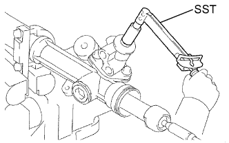
  1. Using SST, recheck the total preload.

    Torque:
    Preload for 2WD (turning):
    0.8 to 1.6 N*m{ 8.2 to 1.6 kgf*cm , 1.1 to 14.2 in.*lbf }
    Preload for 4WD (turning):
    1.0 to 1.8 N*m{ 10.2 to 18.4 kgf*cm , 8.9 to 15.9 in.*lbf }

    SST
    09616-00011  

  1. Remove the RH and LH rack ends.


8. INSPECT POWER STEERING RACK


    G038615E01
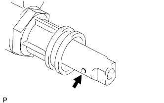
  1. Insert a wire 20 mm (0.79 in.) into the vent hole of the steering rack, and ensure that the vent hole is not clogged with grease.

    NOTICE:
    If the hole is clogged, the pressure inside the boot will change after it is assembled and the steering wheel is turned.


9. INSTALL STEERING RACK END SUB-ASSEMBLY


    C058310E01
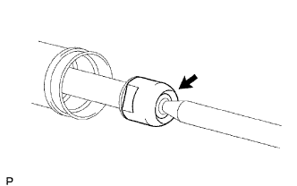
  1. Install 2 new claw washers to the power steering rack while aligning the notch on the steering rack end with the claw.

  1. Temporarily install the 2 steering rack ends to the power steering rack.

  1. Fill up the ball joint of the steering rack ends with MP grease.


    G038605E01
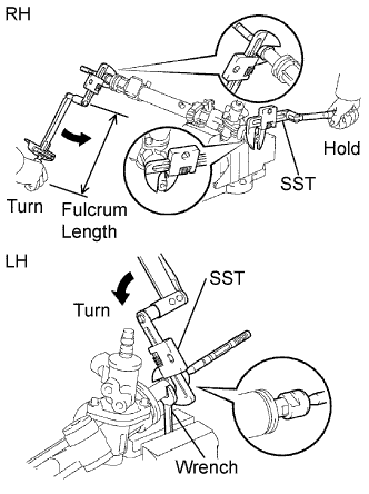
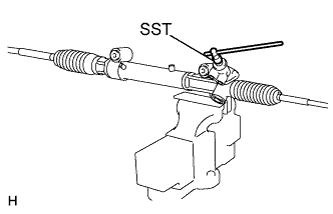
  1. Using SST, install the power steering rack end (LH side) to the power steering rack.

    SST
    09922-10010  

    Torque:
    103 N*m{ 1050 kgf*cm , 76 ft.*lbf } for use without SST
    93.6 N*m{ 954 kgf*cm , 69 ft.*lbf } for use with SST

    NOTICE:
    1. Rotate SST in the direction shown in the illustration.
    2. Use a torque wrench with a fulcrum length of 345 mm (13.58 in.).

  1. Using SST and a wrench, install the power steering rack (LH side).

    SST
    09922-10010  

    Torque:
    103 N*m{ 1050 kgf*cm , 76 ft.*lbf } for use without SST
    93.6 N*m{ 954 kgf*cm , 69 ft.*lbf } for use with SST

    NOTICE:
    1. Rotate SST in the direction shown in the illustration.
    2. Use a torque wrench with a fulcrum length of 345 mm (13.58 in.).


    C035928E01
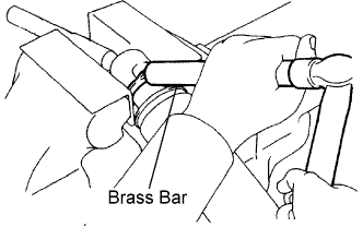
  1. Using a brass bar and hammer, stake the 2 claw washers (LH and RH side).

    NOTICE:
    Do not strike the steering rack.


10. INSTALL STEERING RACK BOOT LH
  1. Install the boot.

    NOTICE:
    Be careful not to damage or twist the boot.


11. INSTALL STEERING RACK BOOT RH

HINT:
Use the same procedures described for the LH side.


12. INSTALL STEERING RACK BOOT CLAMP LH


    G039372E01
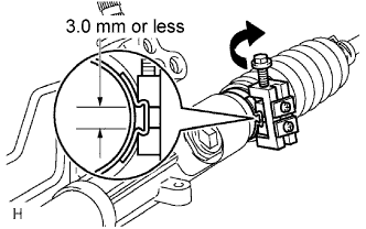
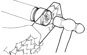
  1. Using SST, tighten the rack boot clamp, as shown in the illustration.

    SST
    09240-00020  
    09521-24010  

    Clearance:
    3.0 mm (0.118 in.) or less

    NOTICE:
    Be careful not to damage the boot.

    HINT:
    Mark the RH and LH boots.

    NOTICE:
    If the clamp is damaged, replace it with a new one.


13. INSTALL STEERING RACK BOOT CLAMP RH

HINT:
Use the same procedures described for the LH side.


14. INSTALL STEERING RACK BOOT CLIP LH
  1. Using pliers, install the clip.


15. INSTALL STEERING RACK BOOT CLIP RH

HINT:
Use the same procedures described for the LH side.


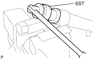
16. INSTALL POWER STEERING GEAR ASSEMBLY


    G100354E01
  1. Using SST, check that the rack boot stretches smoothly when the control valve shaft is being rotated.

    SST
    09616-00011  


    G035024E02
  1. Apply MP grease as shown in the illustration.

  1. Install the dust cover.


17. INSTALL STEERING TURN PRESSURE TUBE (for 2WD)


    G100363E01
  1. Apply power steering fluid to 2 new O-rings. Using SST, install the 2 O-rings and the LH turn pressure tube.

    SST
    09023-38201  

    Torque:
    12.5 N*m{ 127 kgf*cm , 9 ft.*lbf } for use without SST
    11.9 N*m{ 121 kgf*cm , 9 ft.*lbf } for use with SST

    HINT:
    1. Use a torque wrench with a fulcrum length of 345 mm (13.58 in.).
    2. This torque value is effective when SST is parallel to the torque wrench.

  1. Apply power steering fluid to 2 new O-rings. Using SST, install the 2 O-rings and the RH turn pressure tube.

    SST
    09023-38201  

    Torque:
    12.5 N*m{ 127 kgf*cm , 9 ft.*lbf } for use without SST
    11.9 N*m{ 121 kgf*cm , 9 ft.*lbf } for use with SST

    HINT:
    1. Use a torque wrench with a fulcrum length of 345 mm (13.58 in.).
    2. This torque value is effective when SST is parallel to the torque wrench.


18. INSTALL STEERING TURN PRESSURE TUBE (for 4WD)


G100365E01
  1. Apply power steering fluid to 2 new O-rings. Using SST, install the 2 O-rings and the LH turn pressure tube.

    SST
    09023-38201  

    Torque:
    12.5 N*m{ 127 kgf*cm , 9 ft.*lbf } for use without SST
    11.9 N*m{ 121 kgf*cm , 9 ft.*lbf } for use with SST

    HINT:
    1. Use a torque wrench with a fulcrum length of 345 mm (13.58 in.).
    2. This torque value is effective when SST is parallel to the torque wrench.

  1. Apply power steering fluid to 2 new O-ring. Using SST, install the O-ring and one side of the RH turn pressure tube.

    SST
    09023-38201  

    Torque:
    12.5 N*m{ 127 kgf*cm , 9 ft.*lbf } for use without SST
    11.9 N*m{ 121 kgf*cm , 9 ft.*lbf } for use with SST

    HINT:
    1. Use a torque wrench with a fulcrum length of 345 mm (13.58 in.).
    2. This torque value is effective when SST is parallel to the torque wrench.

  1. Apply power steering fluid to new O-ring. Install the O-ring and the RH turn pressure tube.

    Torque:
    29.4 N*m{ 300 kgf*cm , 22 ft.*lbf }