STEERING LINKAGE > DISASSEMBLY |
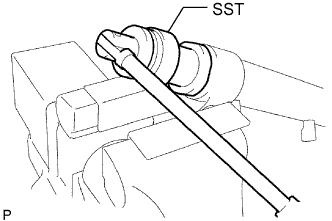
| 1. FIX POWER STEERING LINK ASSEMBLY |
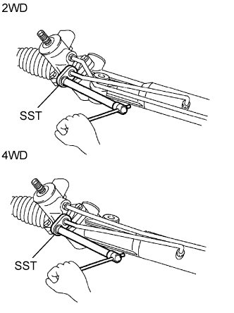 |
Using SST, remove the 2 turn pressure tubes.
 |
Using SST, fix the steering link between aluminum plates in a vise, as shown in the illustration.
| 2. REMOVE TIE ROD END SUB-ASSEMBLY LH |
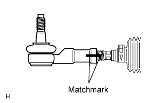 |
Place matchmarks on the tie rod end, lock nut and rack end.
Loosen the lock nut and remove the tie rod end and lock nut.
| 3. REMOVE TIE ROD END SUB-ASSEMBLY RH |
| 4. REMOVE STEERING RACK BOOT CLAMP LH |
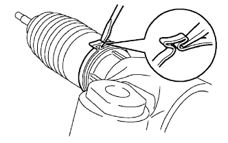 |
Using pliers and a screwdriver, loosen the clamp.
| 5. REMOVE STEERING RACK BOOT CLAMP RH |
| 6. REMOVE STEERING RACK BOOT CLIP LH |
Using pliers, remove the clip.
| 7. REMOVE STEERING RACK BOOT CLIP RH |
| 8. REMOVE STEERING RACK BOOT LH |
| 9. REMOVE STEERING RACK BOOT RH |
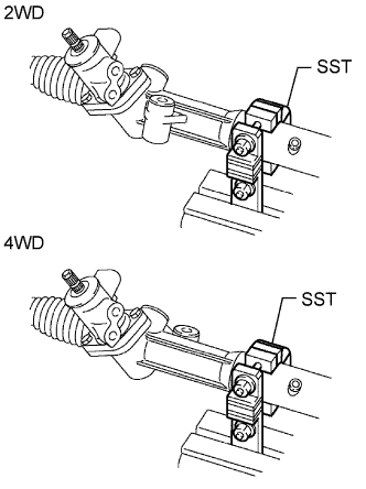
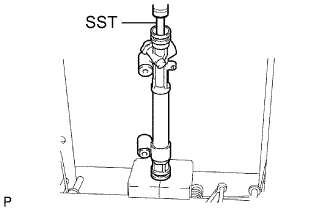
| 10. REMOVE STEERING RACK END SUB-ASSEMBLY |
 |
Using a screwdriver and hammer, stake back the washer.
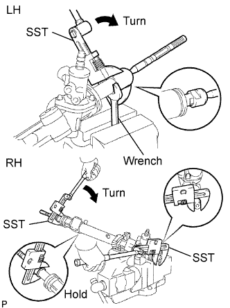 |
Using a wrench, hold the steering rack (LH side).
Using SST, remove the steering rack end (LH side) from the power steering rack.
Using SST, remove the steering rack end (RH side) from the power steering rack.
Remove the 2 claw washers.
| 11. REMOVE RACK GUIDE |
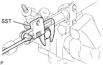 |
Using SST, remove the lock nut.
Remove the claw washer.
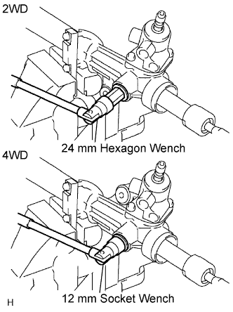 |
2WD:
Using a 24 mm hexagon wrench, remove the rack guide spring cap.
4WD:
Using a 12 mm socket wrench, remove the rack guide spring cap.
Remove the spring and rack guide.
| 12. REMOVE POWER STEERING CONTROL VALVE |
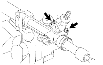 |
Remove the 2 bolts.
Pull out the control valve from the rack housing.
| 13. REMOVE CYLINDER END STOPPER |
 |
Using SST, remove the stopper.
| 14. REMOVE STEERING RACK AND OIL SEAL |
 |
Using SST, press out the steering rack and oil seal.
Remove the oil seal from the steering rack.
| 15. INSPECT POWER STEERING RACK |
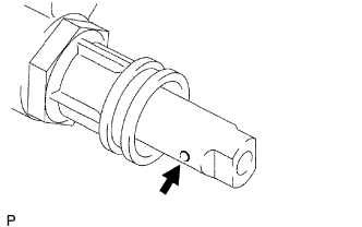 |
Insert a wire 20 mm (0.79 in.) into the vent hole of the steering rack and ensure that the vent hole is not clogged with grease.
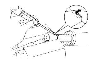
| 16. INSPECT TIE ROD END SUB-ASSEMBLY LH |
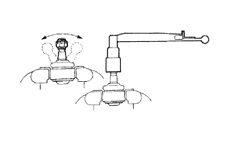 |
Move the ball joint stud back and forth 5 times as shown in the illustration, before installing the nut.
Using a torque wrench, turn the nut continuously at a rate of 2 to 4 seconds per turn and take the torque reading on the 5th turn.
| 17. INSPECT TIE ROD END SUB-ASSEMBLY RH |
| 18. REMOVE STEERING RACK PISTON RING |
Using a screwdriver, remove the teflon ring and O-ring from the steering rack.
