STEERING LINKAGE > REMOVAL |
| 1. PRECAUTION |
| 2. DISCONNECT CABLE FROM NEGATIVE BATTERY TERMINAL |
| 3. PLACE FRONT WHEEL FACING STRAIGHT AHEAD |
| 4. REMOVE STERRING PAD ASSEMBLY |
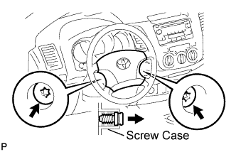 |
Straighten the front wheels.
Using a T30 "torx" socket, loosen the 2 screws until the groove along each screw circumference catches on the screw case.
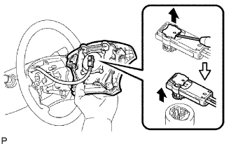 |
Pull out the steering pad from the steering wheel and support the steering pad with one hand as shown in the illustration.
Using a screwdriver, disconnect the airbag connector.
Disconnect the horn connector and remove the steering pad.
| 5. REMOVE STEERING WHEEL ASSEMBLY |
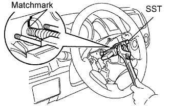 |
Remove the steering wheel set nut.
Place matchmarks on the steering wheel and main shaft.
Using SST, remove the steering wheel.
| 6. REMOVE STEERING COLUMN COVER LOWER |
 |
Remove the 3 screws and cover lower.
| 7. REMOVE STEERING COLUMN COVER UPPER |
| 8. REMOVE WINDSHIELD WIPER SWITCH ASSEMBLY |
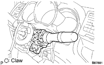 |
Disconnect the connectors.
Detach the claw and remove the wiper switch.
| 9. REMOVE HEADLIGHT DIMMER SWITCH ASSEMBLY |
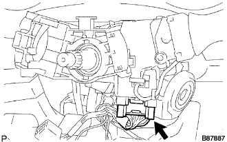 |
Disconnect the connector.
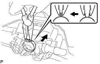 |
Using needle-nose pliers, remove the band clamp as shown in the illustration.
 |
Using a screwdriver, detach the claws and remove the switch.
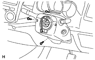
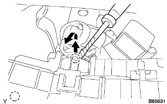
| 10. REMOVE SPIRAL CABLE SUB-ASSEMBLY |
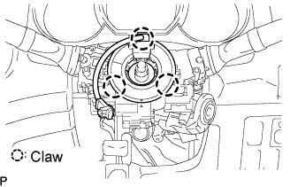 |
Disconnect the connectors from the spiral cable.
Detach the 3 claws and remove the spiral cable.
| 11. REMOVE FRONT WHEEL |
| 12. REMOVE NO. 2 ENGINE UNDER COVER (for 4WD) |
Remove the 4 bolts and under cover.
| 13. REMOVE NO. 1 ENGINE UNDER COVER (for 4WD) |
Remove the 4 bolts and under cover.
| 14. REMOVE FRONT SIDE MEMBER TO FRONT SUSPENSION CROSSMEMBER BRACE |
Remove the 8 bolts and crossmember brace.
| 15. REMOVE STABILIZER BAR FRONT |
Remove the stabilizer bar front from the vehicle body.
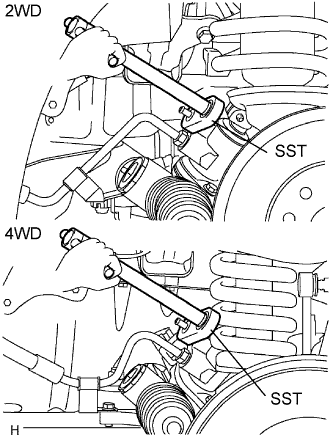
| 16. DISCONNECT TIE ROD END SUB-ASSEMBLY LH |
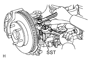 |
Remove the cotter pin and nut.
Using SST, disconnect the tie rod end from the steering knuckle arm.
| 17. DISCONNECT TIE ROD END SUB-ASSEMBLY RH |
| 18. REMOVE NO. 2 STEERING INTERMEDIATE SHAFT SUB-ASSEMBLY |
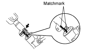 |
Make matchamrks on the intermediate shaft and steering link.
Remove the bolt and intermediate shaft from the steering link.
| 19. DISCONNECT PRESSURE FEED TUBE ASSEMBLY |
 |
Using SST, loosen the flare nut and disconnect the pressure feed tube.
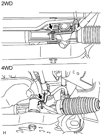 |
Remove the bolt and disconnect the pressure feed tube from the steering link.
| 20. DISCONNECT STEERING GEAR OUTLET RETURN TUBE |
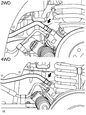 |
Remove the clip and disconnect the return hose.
 |
Using SST, disconnect the outlet return tube.
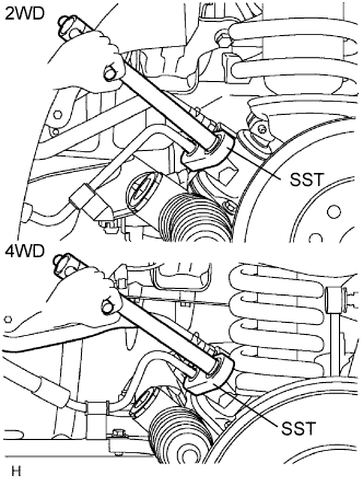
| 21. REMOVE POWER STEERING LINK ASSEMBLY |
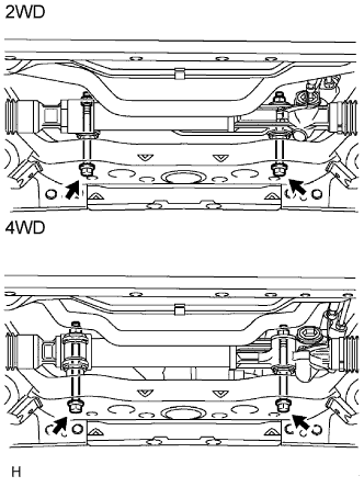 |
Fix the 2 nuts in place and remove the 2 bolts. Then remove the link from the frame.
