STEERING LINKAGE > INSTALLATION |
| 1. INSTALL TIE ROD END SUB-ASSEMBLY LH |
Screw the lock nut and tie rod end onto the rack end until the matchmarks are aligned.
After adjusting toe-in, torque the nut.
| 2. INSTALL TIE ROD END SUB-ASSEMBLY RH |
| 3. INSTALL POWER STEERING LINK ASSEMBLY |
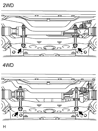 |
Install the steering link with the 2 bolts and 2 nuts.
| 4. INSTALL STABILIZER BAR FRONT |
Install the stabilizer bar front to the vehicle body.
| 5. STABILIZE SUSPENSION |
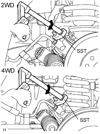
| 6. CONNECT STEERING GEAR OUTLET RETURN TUBE |
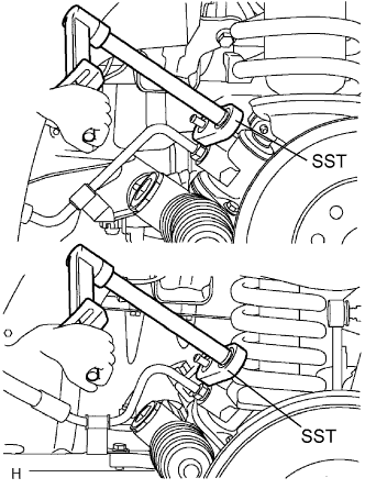 |
Using SST, connect the outlet return tube.
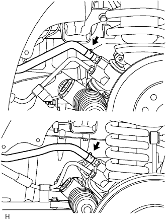 |
Install the hose with the clip.
| 7. CONNECT PRESSURE FEED TUBE ASSEMBLY |
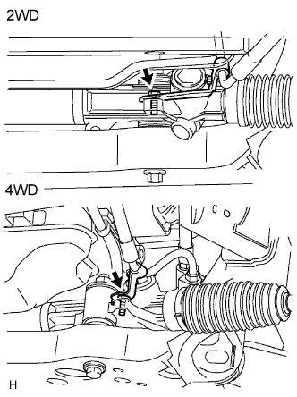 |
Install the pressure feed tube to the steering link with the bolt.
 |
Using SST, tighten the flare nut and connect the pressure feed tube.
| 8. FULLY TIGHTEN NO. 2 STEERING INTERMEDIATE SHAFT SUB-ASSEMBLY |
| 9. CONNECT TIE ROD END SUB-ASSEMBLY LH |
Connect the tie rod end to the steering knuckle arm with the nut.
Install the cotter pin.
| 10. CONNECT TIE ROD END SUB-ASSEMBLY RH |
| 11. INSTALL FRONT SIDE MEMBER TO FRONT SUSPENSION CROSSMEMBER BRACE |
Install the crossmember brace with the 8 bolts.
| 12. INSTALL NO. 1 ENGINE UNDER COVER (for 4WD) |
Install the under cover with the 4 bolts.
| 13. INSTALL NO. 2 ENGINE UNDER COVER (for 4WD) |
Install the under cover with the 4 bolts.
| 14. INSTALL FRONT WHEEL |
| 15. PLACE FRONT WHEELS FACING STRAIGHT AHEAD |
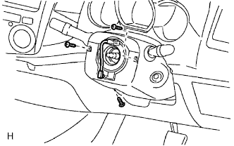
| 16. INSTALL WINDSHIELD WIPER SWITCH ASSEMBLY |
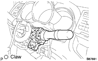 |
Attach the claw to install the wiper switch.
Connect the connectors.
| 17. INSTALL HEADLIGHT DIMMER SWITCH ASSEMBLY |
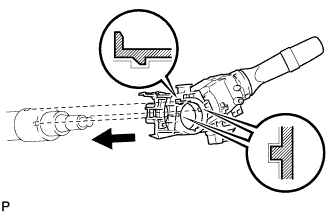 |
Install the headlight dimmer switch with the claw as shown in the illustration.
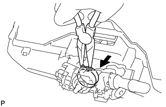 |
Install the headlight dimmer switch with the clamp.
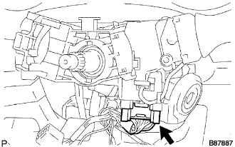 |
Connect the connector.
| 18. INSTALL SPIRAL CABLE SUB-ASSEMBLY |
| 19. INSTALL STEERING COLUMN COVER UPR |
| 20. INSTALL STEERING COLUMN COVER LWR |
 |
Install the cover lower with the 3 screws.
| 21. INSTALL STEERING WHEEL ASSEMBLY |
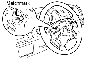 |
Align the matchmarks on the steering wheel and main shaft.
Install the steering set nut.
| 22. INSPECT STEERING WHEEL CENTER POINT |
| 23. INSTALL STEERING PAD ASSEMBLY |
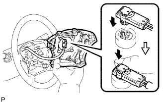 |
Support the steering pad with one hand as shown in the illustration.
Connect the airbag connector.
Connect the horn connector.
Install the steering pad after confirming that the circumference grooves of the screws are caught on the screw case.
Using a T30 "torx" socket, install the 2 screws.
| 24. INSPECT STEERING PAD ASSEMBLY |
Check for cuts, cracks or discoloration on the steering pad outer surface and in the grooved portion.
Check that the horn sounds.
| 25. CONNECT CABLE TO NEGATIVE BATTERY TERMINAL |
| 26. PERFORM INITIALIZATION |
Perform initialization (Click here).
| 27. INSPECT SRS WARNING LIGHT |
Check SRS warning light (Click here).
| 28. ADD POWER STEERING FLUID |
 |
Keep the vehicle level.
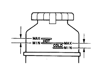
With the engine stopped, check the power steering fluid level in the oil reservoir. If necessary, add power steering fluid.
Start the engine and run it at idle.
Turn the steering wheel to the left or right full lock position, and then the wheel to the opposite full lock position. Repeat several times to raise fluid temperature.
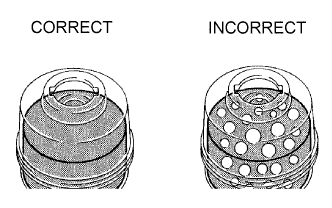 |
Check for foaming or emulsification. If foaming or emulsification is identified, bleed air from the power steering system.
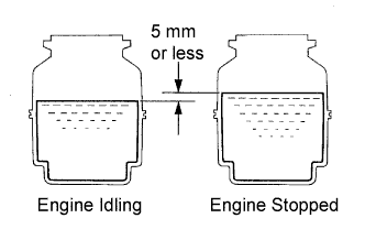 |
With the engine idling, measure the fluid level in the oil reservoir.
Stop the engine.
Wait a few minutes and remeasure the fluid level in the oil reservoir.
Check the fluid level.
| 29. BLEED AIR FROM POWER STEERING SYSTEM |
Check the fluid level.
Jack up the front of the vehicle and support it with stands.
Turn the steering wheel.
With the engine stopped, turn the steering wheel slowly from lock to lock several times.
Lower the vehicle.
Start the engine. Run the engine at idle for a few minutes.
Turn the steering wheel.
With the engine idling, turn the steering wheel to the left or right full lock position and hold it there for 2 to 3 seconds. Then turn the steering wheel to the opposite full lock position and hold it there for 2 to 3 seconds.
Repeat the step above several times.
Stop the engine.
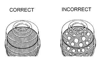 |
Check for foaming or emulsification. If the system has to be bled twice because of forming or emulsification, check for fluid leaks in the system.
Check the fluid level.
| 30. CHECK FOR POWER STEERING FLUID LEAKAGE |
Disconnect the pressure feed tube (for TR series engine, Click here; for 1GR-FE, Click here; for KD series engine, Click here).
Connect SST as shown in the illustration on the next page.
Bleed air from the power steering system.
Start the engine and run it at idle.
Turn the steering wheel to the left or right full lock position. Then turn the wheel to the opposite full lock position. Repeat this several times to raise fluid temperature.
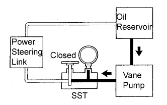 |
With the engine idling, close the valve of SST and observe the reading on SST.
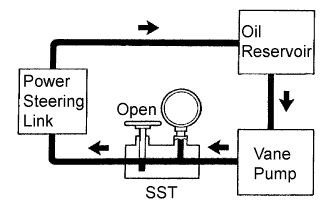 |
With the engine idling, fully open the valve.
Measure the fluid pressure at engine speeds of 1,000 rpm and 3,000 rpm.
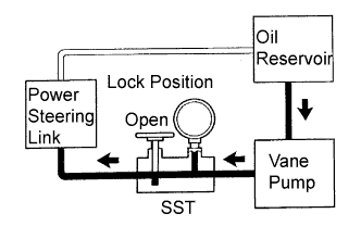 |
With the engine idling and the valve fully opened, turn the steering wheel to the full lock position.
Disconnect SST.
Connect the pressure feed tube (for TR series engine, Click here; for 1GR-FE, Click here; for KD series engine, Click here).
Bleed air from the power steering system.
| 31. INSPECT AND ADJUST FRONT WHEEL ALIGNMENT |
Inspect and adjust front wheel alignment (Click here).
