OIL PUMP > INSPECTION |
| 1. REMOVE OIL PUMP COVER |
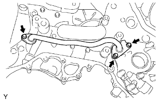 |
Remove the 3 bolts and oil pipe.
Remove the 2 O-rings.
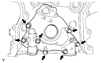 |
Remove the 7 bolts, oil pump cover, drive rotor and driven rotor.
| 2. REMOVE OIL PUMP RELIEF VALVE |
Remove the plug, spring and relief valve.
| 3. INSPECT OIL PUMP RELIEF VALVE |
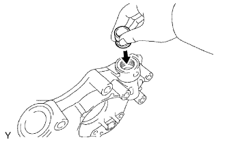 |
Coat the valve with the engine oil and check that it falls smoothly into the valve hole by its own weight.
If the does not, replace the relief valve. If necessary, replace the oil pump assembly.
| 4. INSPECT OIL PUMP ROTOR SET |
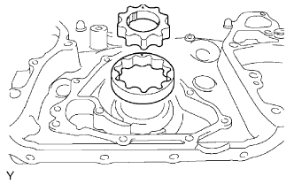 |
Place the drive and driven rotors into the timing chain cover with the marks facing upward.
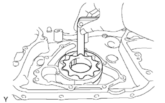 |
Inspect the rotor tip clearance.
Using a feeler gauge, measure the clearance between the drive and driven rotor tips.
| Condition | Clearance |
| Standard | 0.06 to0.16 mm (0.0024 to 0.0063 in.) |
| Maximum | 0.16 mm (0.0063 in.) |
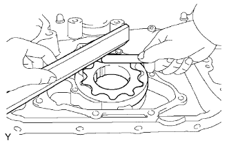 |
Inspect the rotor side clearance.
Using a feeler gauge and precision straightedge, measure the clearance between the rotors and straightedge, as shown in the illustration.
| Condition | Clearance |
| Standard | 0.03 to 0.09 mm (0.0012 to 0.0035 in.) |
| Maximum | 0.09 mm (0.0035 in.) |
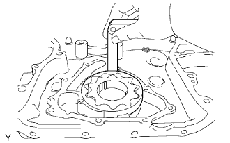 |
Inspect rotor body clearance.
Using a feeler gauge, measure the clearance between the driven roror and body.
| Condition | Clearance |
| Standard | 0.250 to 0.325 mm (0.00098 to 0.0128 in.) |
| Maximum | 0.325 mm (0.0128 in.) |
| 5. INSTALL OIL PUMP RELIEF VALVE |
|
Coat the relief valve with engine oil and insert the relief valve and spring into the valve hole.
Install the relief valve plug.
| 6. INSTALL OIL PUMP COVER |
Apply new engine oil to the drive and driven rorors.
Place the drive and driven rotors into the timing chain cover with the marks facing the oil pump cover side.
|
Install the oil pump cover with the 7 bolts.
Install a new O-ring to the oil pump cover.
Install a new O-ring to the oil pipe.
|
Install the oil pipe with the 3 bolts.
