HEATER SWITCH > INSPECTION |
| 1. INSPECT HEATER SWITCH ASSEMBLY |
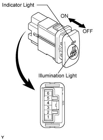 |
Measure the resistance of the switch.
| Tester Connection | Switch Condition | Specified Condition |
| 3 - 4 | ON | Below 1 Ω |
| 3 - 4 | OFF | 10 kΩ or higher |
Apply battery voltage to the switch connector and check that the indicator light illuminates.
| Measurement Connection | Specified Condition |
| Battery positive (+) → Terminal 6 Battery positive (+) → Terminal 5 | Indicator light Illuminates |
Apply battery voltage to the switch connector and check that the illumination light illuminates.
| Measurement Connection | Specified Condition |
| Battery positive (+) → Terminal 1 Battery positive (+) → Terminal 2 | Illumination light Illuminates |
