CAMSHAFT (for Bank 1) > REMOVAL |
| 1. DISCONNECT BATTERY NEGATIVE TERMINAL |
| 2. DISCHARGE FUEL SYSTEM PRESSURE |
Disconnect the cable from the negative (-) battery terminal.
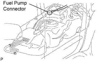 |
Disconnect the fuel pump connector.
Connect the cable to the negative (-) battery terminal.
Start the engine. After the engine has stopped on its own, turn the ignition switch OFF.
Crank the engine again, then check that the engine does not start.
Loosen the fuel tank cap, then discharge the pressure in the fuel tank completely.
Connect the fuel pump connector.
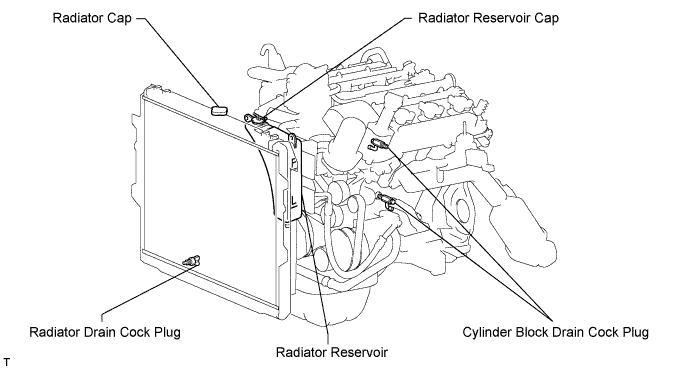
| 3. DRAIN ENGINE COOLANT |
Remove the radiator cap.
Loosen the 2 cylinder block drain cock plugs and radiator drain plug, and then the coolant.
| 4. REMOVE DRIVE BELT |
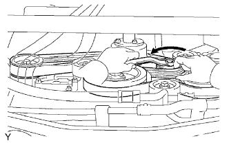 |
While releasing the belt tension by turning the belt tensioner counterclockwise, remove the V-ribbed belt from the belt tensioner.
| 5. REMOVE V-BANK COVER |
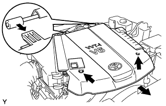 |
Remove the 2 nuts and the V-bank cover.
| 6. REMOVE NO. 2 VENTILATION HOSE |
 |
| 7. REMOVE AIR CLEANER |
 |
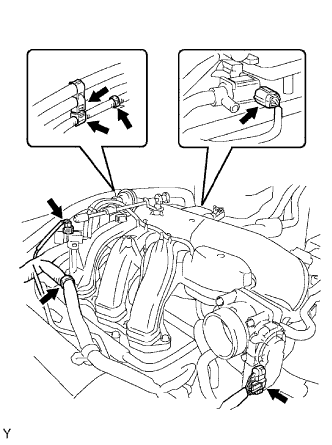
Disconnect the vacuum hose.
Disconnect the MAF meter connector.
Remove the 2 wire harness clamps.
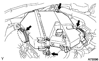 |
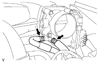
Loosen the 2 hose clamps.
Remove the 2 bolts and air cleaner.
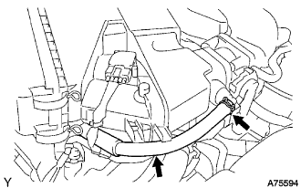
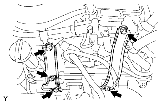
| 8. REMOVE INTAKE AIR SURGE TANK |
 |
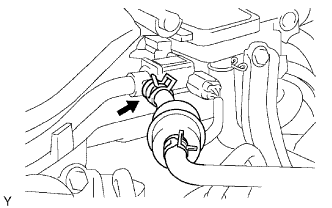
Disconnect the 2 water by-pass hose.
 |
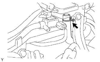
Disconnect the fuel vapor feed hose.
 |
Disconnect the ventilation hose.
 |
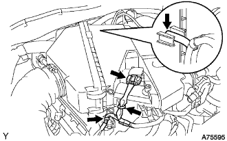
Disconnect the 2 VSV connectors.
Disconnect the throttle body with motor connector.
Separate the 3 wire harness clamps and hose clamp.
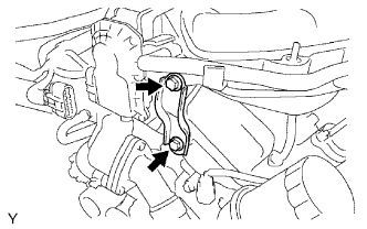 |
Remove the 2 bolts and throttle body bracket.
 |
Remove the bolt and oil baffle plate.
Remove the 4 bolts and 2 surge tank stays.
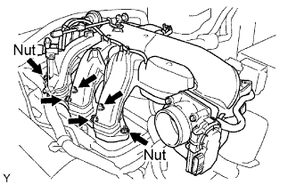 |
Remove the 2 nuts.
Using an 8 mm socket hexagon wrench, remove the 4 bolts, intake air surge tank and gasket.
| 9. REMOVE IGNITION COIL |
| 10. REMOVE CYLINDER HEAD COVER RH |
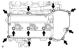 |
Remove the 10 bolts, 3 seal washers, 2 nuts, cylinder head cover and gasket.
| 11. REMOVE CYLINDER HEAD COVER LH |
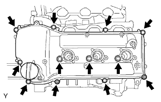 |
Remove the 10 bolts, 3 seal washers, 2 nuts, cylinder head cover and gasket.
| 12. SET NO. 1 CYLINDER TO TDC/COMPRESSION |
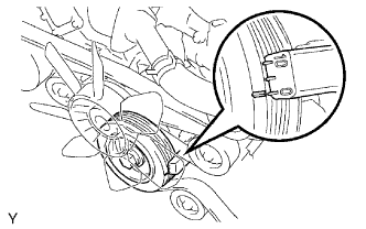 |
Turn the crankshaft pulley, and align the notch with timing mark 0 of the timing chain cover.
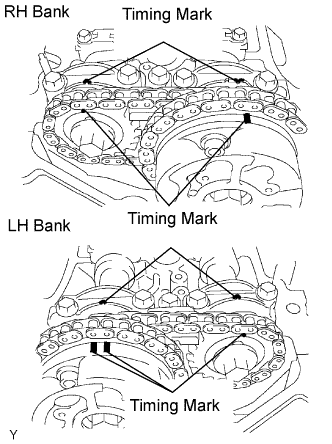 |
Check that the timing marks of the camshaft timing gears are aligned with the timing marks of the bearing cap as shown in the illustration.
If the timing marks are not aligned, turn the crankshaft 1 complete revolution (360°) and align the timing marks as stored above.
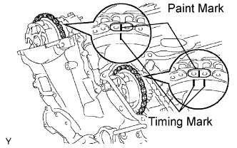 |
Place paint marks on the No. 1 chain links that correspond with the timing marks of the camshaft timing gears.
| 13. REMOVE NO. 1 CHAIN TENSIONER |
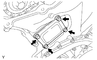 |
Remove the 4 bolts, timing chain cover plate and gasket.
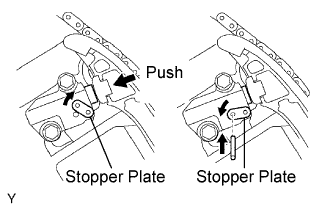 |
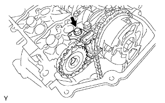
While turning the stopper plate of the tensioner clockwise, push in the plunger of the chain tensioner as shown in the illustration.
While turning the stopper plate of the tensioner counterclockwise, insert a diameter of 3.5 mm (0.138 in.) bar into the holes on the stopper plate and tensioner to fix the stopper plate.
Remove the 2 bolts and chain tensioner.
| 14. REMOVE NO. 2 CAMSHAFT |
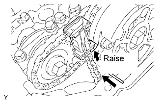 |
While raising up the No. 2 chain tensioner, insert a diameter of 1.0 mm (0.039 in.) into the hole to fix it.
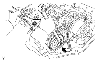 |
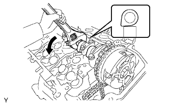
Hold the hexagonal portion of the No. 2 camshaft with a wrench, and remove the camshaft timing gear set bolt.
Separate the camshaft timing gear from the No. 2 camshaft.
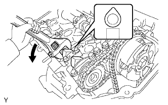 |
Rotate the camshaft counterclockwise using the wrench so that the cam lobes of No. 1 cylinder faces upward as shown in the illustration.
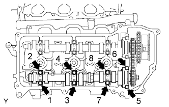 |
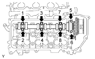
Uniformly loosen and remove the 8 bearing cap bolts in several passes in the sequence shown in the illustration.
Remove the 4 bearing caps and No. 2 camshaft.
| 15. REMOVE NO. 2 CHAIN TENSIONER |
 |
Remove the No. 2 chain tensioner bolt, and then remove the No. 2 chain tensioner and camshaft timing gear.
| 16. REMOVE NO. 1 CAMSHAFT |
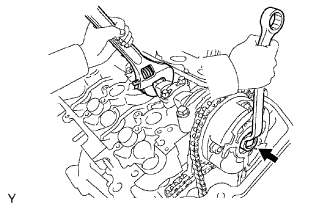 |
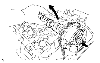
Hold the hexagonal portion of the No. 1 camshaft with a wrench, and loosen the camshaft timing gear set bolt.
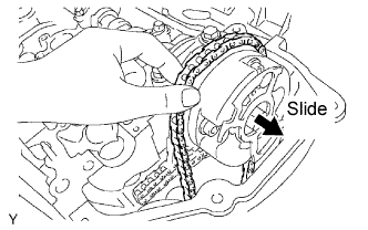 |
Slide the camshaft timing gear and separate the No. 1 chain from the camshaft timing gear.
 |
Rotate the No. 1 camshaft counterclockwise using the wrench so that the cam lobes of No. 1 cylinder faces downward as shown in the illustration.
 |
Loosen and remove the 8 bearing cap bolts in several passes in the sequence shown in the illustration.
Remove the 4 bearing caps.
 |
Remove the camshaft timing gear set bolt with the No. 1 camshaft is lifted up, and then remove the No. 1 camshaft and camshaft timing gear with No. 2 chain.
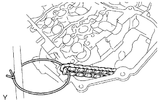 |
Tie the No. 1 chain with a string as shown in the illustration.
