DTC P0660 Intake Manifold Tuning Valve Control Circuit / Open (Bank 1) |
| DTC No. | DTC Detection Condition | Trouble Area |
| P0660 | Following conditions are met simultaneously for 0.5 sec. or more (2 trip detection logic) (a) Voltage of terminal ACIS of the ECM is low when VSV is OFF (b) Engine has started |
|
| 1.PERFORM ACTIVE TEST (OPERATIVE VSV FOR ACIS) |
 |
Disconnect the vacuum hose.
Connect the intelligent tester to the DLC3.
Start the engine and turn the tester ON.
Enter the following menus: Powertrain / Engine and ECT / Active Test / Activate the VSV for Intake Control.
Press the right of left button.
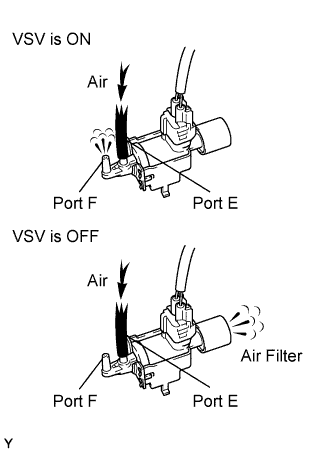
Check if the disconnected port sucks air when operating the VSV for ACIS using the intelligent tester.
| Tester Operation | Specified Condition |
| VSV is ON | Air from port E flows out through port F |
| VSV is OFF | Air from port E flows out through the air filter |
|
| ||||
| NG | |
| 2.INSPECT VSV FOR ACIS (OPERATION) |
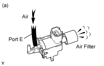 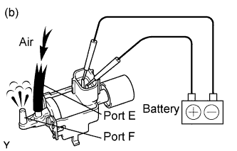 |
Check that air flows from port E to the air filter.
Apply battery positive voltage across the terminals.
Check that air flows from port E to port F.
|
| ||||
| OK | |
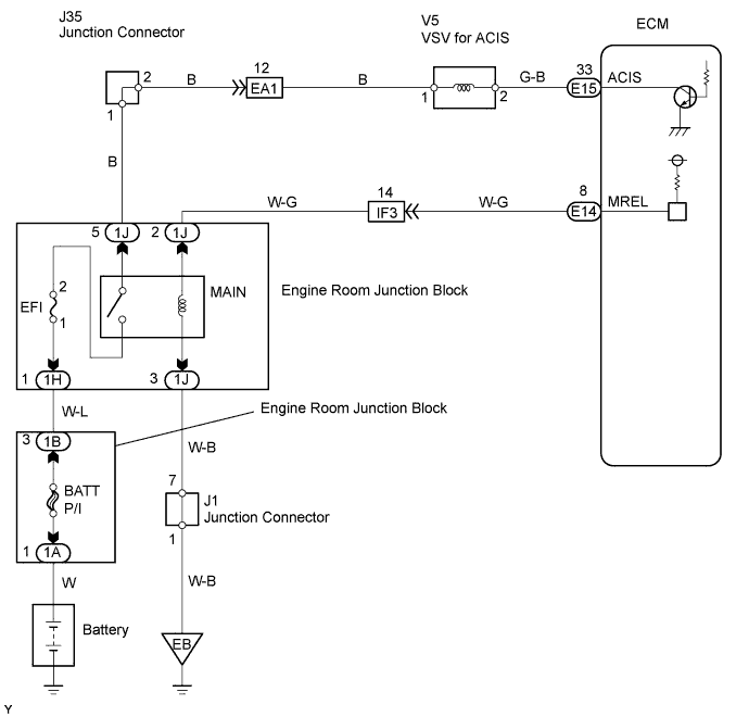
| 3.CHECK WIRE HARNESS (VSV FOR ACIS - ECM, VSV FOR ACIS - EFI RELAY) |
 |
Check the wire harness between the VSV for ACIS and ECM.
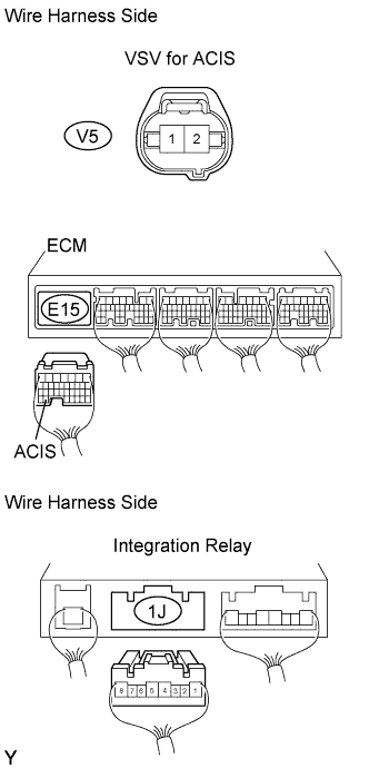
Disconnect the V5 VSV for ACIS connector.
Disconnect the E15 ECM connector.
Measure the resistance of the wire harness side connectors.
| Tester Connection | Specified Condition |
| V5-2 (ACIS) - E15-33 (ACIS) | Below 1 Ω |
| V5-2 (ACIS) or E15-33 (ACIS) - Body ground | 10 kΩ or higher |
Check the wire harness between the VSV for ACIS and integration relay.
Disconnect the V15 VSV for ACIS connector.
Disconnect the 1J integration relay connector from engine room junction block.
Measure the resistance of the wire harness side connectors.
| Tester Connection | Specified Condition |
| V5-1 (ACIS) - 1J-5 | Below 1 Ω |
|
| ||||
| OK | ||
| ||
