INTAKE AIR CONTROL SYSTEM > ON-VEHICLE INSPECTION |
| 1. CHECK INTAKE AIR SYSTEM |
Check for leakage or clogging between the air cleaner housing and turbocharger inlet, and between the turbocharger outlet and cylinder head.
| Condition | Operation |
| Clogged air cleaner | Clean or replace |
| Collapsed or deformed hoses | Repair or replace |
| Leakage from connections | Check each connection and repair |
| Cracks in components | Check and replace |
| 2. CHECK EXHAUST SYSTEM |
Check for leakage or clogging between the cylinder head and turbocharger inlet, and between the turbocharger outlet and exhaust pipe.
| Condition | Operation |
| Deformed components | Repair or replace |
| Foreign matter in passages | Remove |
| Leakage from components | Repair or replace |
| Cracks in components | Check or replace |
| 3. CHECK TURBOCHARGER PRESSURE |
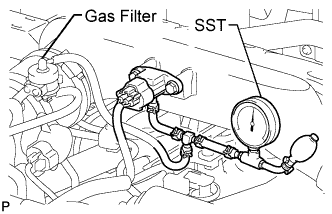 |
Warm up the engine.
Using a 3-way connector, connect SST (turbocharger pressure gauge) to the hose between the manifold absolute pressure sensor and the gas filter leading to the intake air connector.
Depress the clutch pedal, and then fully depress the accelerator pedal. Measure the turbocharging pressure at maximum speed (approximately 4,600 rpm).
| 4. CHECK TURBINE SHAFT ROTATION |
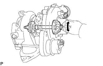 |
Grasp the edge of the turbine shaft and turn it. Check that the turbine shaft turns smoothly.
If the turbine shaft does not turn or is difficult to turn, replace the turbocharger.
| 5. CHECK MANIFOLD ABSOLUTE PRESSURE SENSOR |
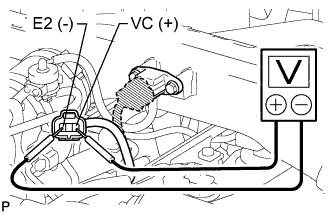 |
Inspect the power source voltage.
Disconnect the pressure sensor connector.
Turn the ignition switch ON.
Measure the voltage between terminals T9-3 (VC (+)) and T9-1 (E2 (-)) of the wire harness side connector.
Turn the ignition switch OFF.
Connect the pressure sensor connector.
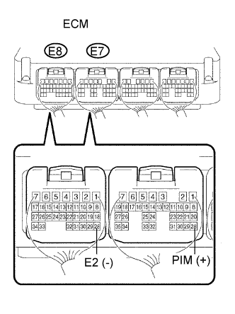 |
Check the power supply.
Turn the ignition switch ON.
Disconnect the vacuum hose from the pressure sensor.
Connect a voltmeter to terminals E7-28 (PIM (+)) and E8-28 (E2 (-)) of the ECM, and measure the output voltage at ambient atmospheric pressure.
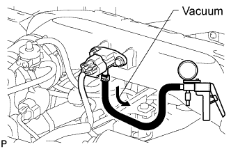 |
Apply a vacuum to the pressure sensor in 13.3 kPa (100 mmHg, 3.94 in.Hg) increments until the pressure reaches 40.0 kPa (300 mmHg, 11.81 in.Hg). Measure the decrease in voltage for each increment.
| Applied Vacuum | Voltage Decrease |
| -13.3 kPa (100 mmHg, 3.94 in.Hg) | 0.1 to 0.4 V |
| -26.6 kPa (199 mmHg, 7.85 in.Hg) | 0.2 to 0.6 V |
| -40 kPa (300 mmHg, 11.81 in.Hg) | 0.4 to 0.8 V |
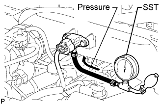 |
Using SST (turbocharger pressure gauge), apply pressure to the pressure sensor in 19.6 kPa (0.20 kgf*cm2, 2.84 psi) increments until the pressure reaches 98.0 kPa (1.00 kgf*cm2, 14.2 psi). Measure the increase in voltage for each increment.
| Applied Pressure | Voltage Increase |
| 19.6 kPa (0.20 kgf*cm2, 2.84 psi) | 0.1 to 0.4 V |
| 39.2 kPa (0.40 kgf*cm2, 5.69 psi) | 0.4 to 0.7 V |
| 58.8 kPa (0.60 kgf*cm2, 8.53 psi) | 0.7 to 1.0 V |
| 78.5 kPa (0.80 kgf*cm2, 11.4 psi) | 1.0 to 1.3 V |
| 98.0 kPa (1.00 kgf*cm2, 14.2 psi) | 1.3 to 1.6 V |
