ENGINE OIL COOLER > REMOVAL |
| 1. DISCONNECT CABLE FROM NEGATIVE BATTERY TERMINAL |
| 2. REMOVE NO. 1 ENGINE UNDER COVER (for 4WD) |
Remove the 4 bolts and under cover.
| 3. REMOVE NO. 2 ENGINE UNDER COVER (for 4WD) |
Remove the 2 bolts and under cover.
| 4. DRAIN ENGINE OIL |
Remove the oil filler cap.
Remove the oil drain plug, and drain the engine oil from the oil pan.
| 5. LOOSEN FUEL TANK ASSEMBLY |
| 6. DRAIN FUEL |
| 7. REMOVE MANIFOLD STAY |
 |
Remove the 2 bolts and stay.
| 8. REMOVE OIL LEVEL GAUGE SUB-ASSEMBLY |
Remove the bolt and gauge.
Remove the O-ring from the gauge.
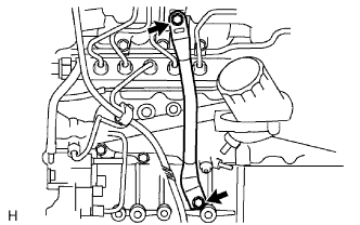
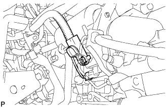
| 9. REMOVE FUEL INLET PIPE SUB-ASSEMBLY |
 |
Remove the bolt and clamp.
Remove the 2 bolts and oil level gauge guide.
 |
Using SST, loosen the union nuts and remove the fuel inlet pipe.
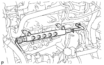
| 10. REMOVE INJECTION PIPE |
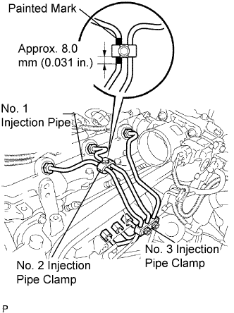 |
Temporarily install the No. 1, No. 2 and No. 3 injection pipes with the union nuts.
Install the No. 2 and No. 3 injection pipe clamps with the bolt and 2 nuts, as shown in the illustration.
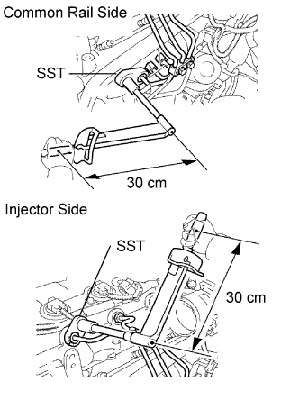 |
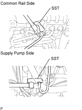
Using SST, tighten the injection pipe union nuts on the common rail side.
Using SST, tighten the injection pipe union nuts on the injector side.
 |
Temporarily install the No. 4 injection pipe with the union nuts.
Install 2 new injection pipe clamps with the 2 bolts.
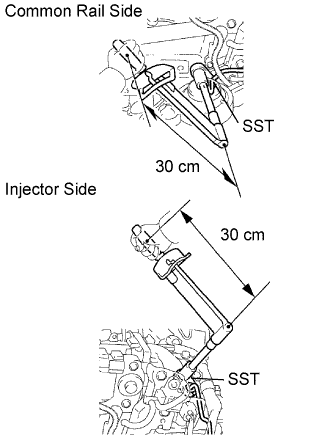 |
Using SST, tighten the injection pipe union nuts on the common rail side.
Using SST, tighten the injection pipe union nuts on the injector side.
| 11. REMOVE OIL FILTER SUB-ASSEMBLY |
Check and clean the oil filter installation surface.
Apply clean engine oil to the gasket of a new oil filter.
Lightly screw the oil filter into place by hand. Tighten it until the gasket contacts the seat.
 |
Using SST, tighten the oil filter. Depending on the work space available, choose from the following.
If enough space is available, use a torque wrench to tighten the oil filter.
If enough space is not available to use a torque wrench, tighten the oil filter 3/4 turn by hand or with a common wrench.
| 12. REMOVE STARTER ASSEMBLY |
 |
Disconnect the starter connector.
Remove the nut and disconnect the starter wire.
Remove the clutch release cylinder.
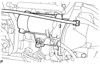 |
Remove the nut, bolt, ground cable and starter.
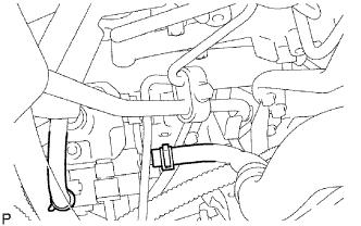
| 13. REMOVE FUEL SUPPLY PUMP ASSEMBLY |
|
Remove the bolt and clamp.
Remove the 2 bolts and oil level gauge guide.
|
Using SST, loosen the union nuts and remove the fuel inlet pipe.
 |
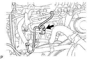
Disconnect the 2 fuel hoses.
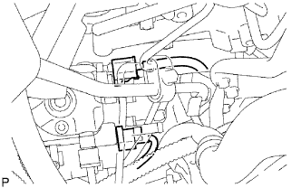 |
Disconnect the 2 connectors.
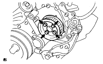 |
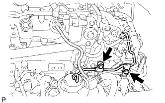
Remove the 4 bolts indicated by the arrows in the illustration.
Remove the No. 2 camshaft timing pulley flange and pump drive shaft pulley.
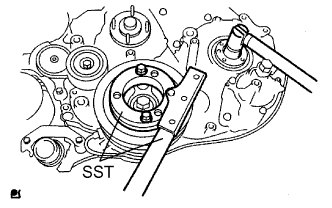 |
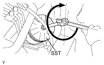
Remove the set nut and O-ring while holding the crankshaft pulley by using SST.
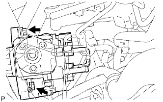 |
Loosen the 2 nuts.
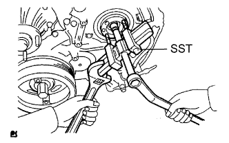 |
Using SST, disconnect the pump from the injection gear.
Remove the 2 nuts and pump.
Remove the O-ring.
| 14. REMOVE COMMON RAIL ASSEMBLY |
 |
Disconnect the fuel pressure sensor connector.
Remove the 2 bolts and common rail.
| 15. REMOVE OIL COOLER COVER SUB-ASSEMBLY |
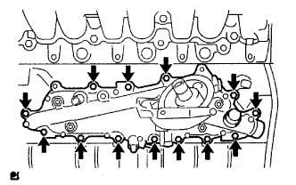 |
Disconnect the oil pressure switch connector and wire harness.
Remove the 13 bolts, 2 nuts and oil cooler cover.
| 16. REMOVE OIL COOLER ASSEMBLY |
Loosen the 4 nuts first.
Partially tap out the oil cooler by tapping each nut head with a plastic-faced hammer.
Remove the 4 nuts, oil cooler and 2 gaskets.
