ENGINE OIL COOLER > INSTALLATION |
| 1. INSTALL OIL COOLER ASSEMBLY |
 |
Install 2 new gaskets to the oil cooler.
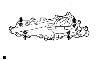
Install the oil cooler to the oil cooler cover with the 4 nuts.
| 2. INSTALL OIL COOLER COVER SUB-ASSEMBLY |
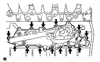 |
Install a new gasket and the oil cooler cover with the 13 bolts and 2 nuts.
Connect the oil pressure connector and install the wire harness.
| 3. INSTALL COMMON RAIL ASSEMBLY |
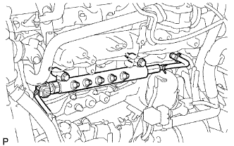 |
Install the common rail with the 2 bolts.
Connect the fuel pressure sensor connector.
| 4. INSTALL FUEL SUPPLY PUMP ASSEMBLY |
 |
Check that the supply pump gear in the timing gear case moves back and forth smoothly.
Install a new O-ring to the pump.
Apply a light coat of engine oil to the O-ring.
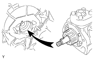 |
Align the set key on the drive shaft with the groove of the injection gear.
 |
Install the pump with the 2 nuts.
Set a new O-ring before tightening the set nut.
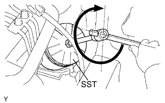
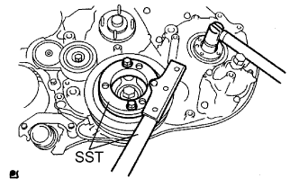 |
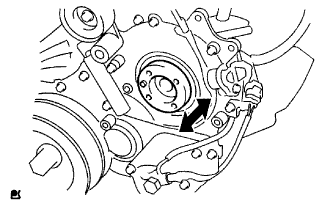
Using SST, hold the crankshaft pulley and install the set nut.
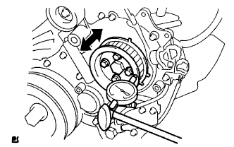 |
Move the pump drive shaft pulley back and forth to check the thrust clearance of the injection pump drive shaft.
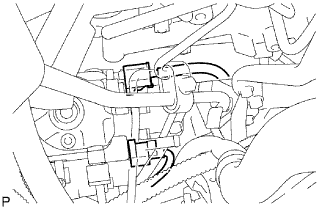 |
Connect the 2 connectors.
 |
Connect the 2 fuel hoses.
 |
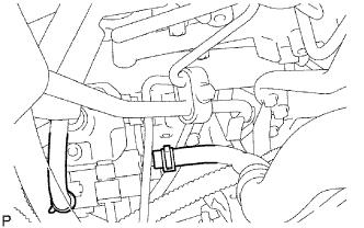
Temporarily install the fuel inlet pipe with the union nuts.
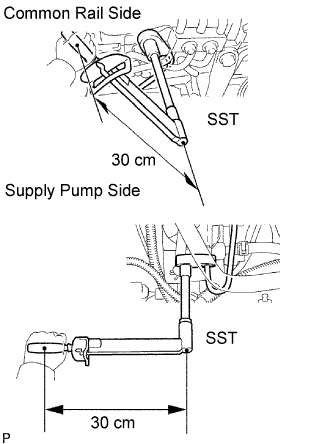
Using SST, tighten the injection pipe union nut on the common rail side.
Using SST, tighten the injection pipe union nut on the supply pump side.
Install the oil level gauge guide with the 2 bolts.
 |
Install the clamp with the bolt.
| 5. INSTALL STARTER ASSEMBLY |
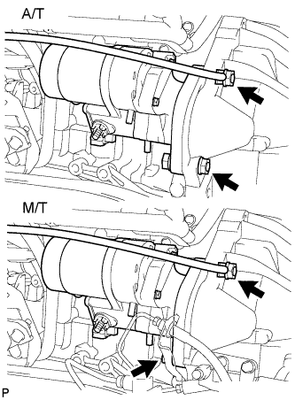 |
A/T:
Install the starter and ground cable with the 2 nuts and bolt.
M/T:
Install the starter and ground cable with the nut and bolt.
Install the starter wire to terminal 30 with the nut.
Connect the starter connector.
A/T:
Install the A/T oil dipstick with the 2 bolts.
M/T:
Install the clutch release cylinder.
| 6. INSTALL OIL FILTER SUB-ASSEMBLY |
Check and clean the oil filter installation surface.
Apply clean engine oil to the gasket of a new oil filter.
Lightly screw the oil filter into place by hand. Tighten it until the gasket contacts the seat.
 |
Using SST, tighten the oil filter. Depending on the work space available, choose from the following.
If enough space is available, use a torque wrench to tighten the oil filter.
If enough space is not available to use a torque wrench, tighten the oil filter 3/4 turn by hand or with a common wrench.
| 7. INSTALL INJECTION PIPE |
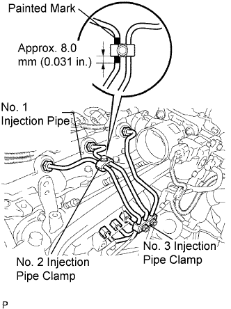 |
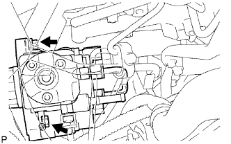
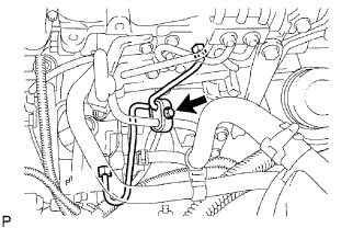
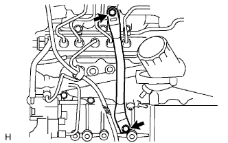
Temporarily install the No. 1, No. 2 and No. 3 injection pipes with the union nuts.
Install the No. 2 and No. 3 injection pipe clamps with the bolt and 2 nuts, as shown in the illustration.
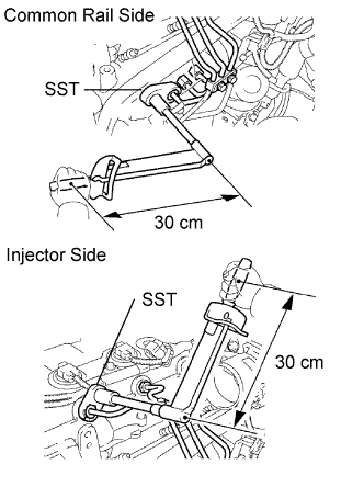 |
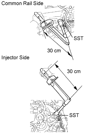
Using SST, tighten the injection pipe union nuts on the common rail side.
Using SST, tighten the injection pipe union nuts on the injector side.
 |
Temporarily install the No. 4 injection pipe with the union nuts.
Install 2 new injection pipe clamps with the 2 bolts.
 |
Using SST, tighten the injection pipe union nuts on the common rail side.
Using SST, tighten the injection pipe union nuts on the injector side.
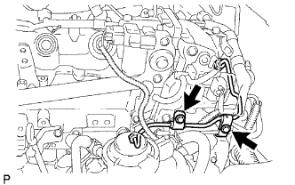
| 8. INSTALL FUEL INLET PIPE SUB-ASSEMBLY |
|
Temporarily install the fuel inlet pipe with the union nuts.
Using SST, tighten the inlet pipe union nut on the common rail side.
Using SST, tighten the inlet pipe union nut on the supply pump side.
Install the oil level gauge guide with the 2 bolts.
|
Install the clamp with the bolt.
| 9. INSTALL OIL LEVEL GAUGE SUB-ASSEMBLY |
Apply clean engine oil to a new O-ring.
Install the O-ring to the dipstick.
Install the level gauge with the bolt.
| 10. INSTALL MANIFOLD STAY |
 |
Install the stay with the 2 bolts.
| 11. ADD FUEL |
| 12. TIGHTEN FUEL TANK CAP ASSEMBLY |
| 13. ADD ENGINE OIL |
| 14. BLEED AIR FROM FUEL SYSTEM |
 |
Using the hand pump, bleed air from the fuel system until pumping becomes difficult.
| 15. CONNECT CABLE TO NEGATIVE BATTERY TERMINAL |
| 16. PERFORM INITIALIZE |
Perform initialization (Click here).
| 17. CHECK FOR FUEL LEAKS |
| 18. CHECK FOR ENGINE OIL LEAKS |
| 19. INSTALL NO. 2 ENGINE UNDER COVER (for 4WD) |
Install the under cover with the 2 bolts.
| 20. INSTALL NO. 1 ENGINE UNDER COVER (for 4WD) |
Install the under cover with the 4 bolts.
