OIL PUMP > REMOVAL |
| 1. DISCONNECT CABLE FROM NEGATIVE BATTERY TERMINAL |
| 2. REMOVE NO. 1 ENGINE UNDER COVER (for 4WD) |
Remove the 4 bolts and under cover.
| 3. REMOVE NO. 2 ENGINE UNDER COVER (for 4WD) |
Remove the 2 bolts and under cover.
| 4. DRAIN ENGINE OIL |
Remove the oil filler cap.
Remove the oil drain plug, and drain the engine oil from the oil pan.
| 5. DRAIN TRANSMISSION OIL |
R151/R151F:
Drain transmission oil (Click here).
G50/G55:
Drain transmission oil (Click here).
| 6. DRAIN ENGINE COOLANT |
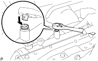 |
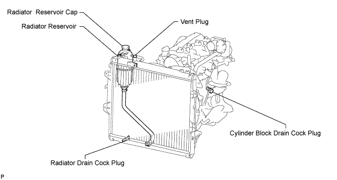
Drain the coolant by removing the reservoir cap and, using a wrench, remove the vent plug.
Loosen the cylinder block drain cock plug and the radiator drain cock plug.
| 7. LOOSEN FUEL TANK CAP ASSEMBLY |
| 8. DRAIN FUEL |
| 9. REMOVE HOOD SUB-ASSEMBLY |
Disconnect the washer nozzle hose from the washer nozzle.
Remove the 4 bolts and hood.
| 10. REMOVE RADIATOR GRILLE |
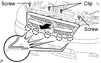 |
Using a clip remover, remove the 2 clips.
Remove the 2 screws.
Pull the radiator grille in the direction indicated by the arrow in the illustration to detach the 5 claws and remove the radiator grille.
| 11. REMOVE BATTERY BRACKET |
| 12. REMOVE BATTERY AND BATTERY TRAY |
| 13. REMOVE AIR CLEANER ASSEMBLY |
| 14. REMOVE RADIATOR ASSEMBLY |
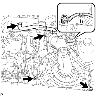 |
Remove the clamp and disconnect the IAT connector.
Loosen the clamp of the turbocharger.
Slide the clamp and disconnect the ventilation hose.
Remove the 2 bolts and air cleaner.
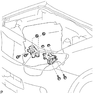
| 15. DISCONNECT HOSES AND CONNECTORS |
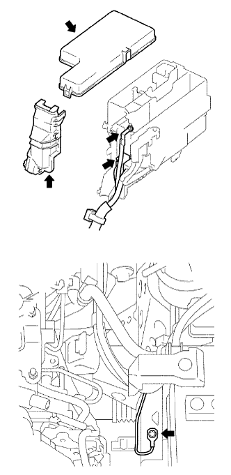 |
Remove the engine room relay block cover (upper).
Remove the No. 1 engine room relay block cover (side).
Remove the nut and disconnect the engine room J/B wire.
Disconnect the 2 engine room junction block connectors.
Remove the bolt and disconnect the ground cable.
 |
Disconnect the 2 injector driver connectors.
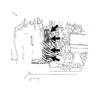 |
Disconnect the 4 ECM connectors.
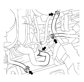 |
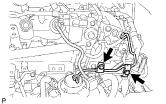
Disconnect the 2 fuel hoses.
Disconnect the vacuum pump hose.
Disconnect the oil reservoir to pump hose.
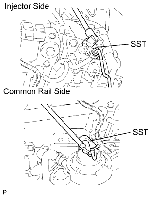
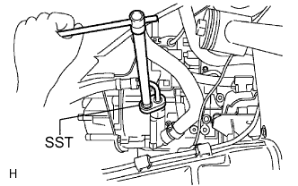 |
Using SST, disconnect the pressure feed tube.
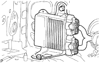
| 16. REMOVE COOLER COMPRESSOR ASSEMBLY |
Remove the 4 bolts and disconnect the cooler compressor.
| 17. REMOVE STARTER ASSEMBLY |
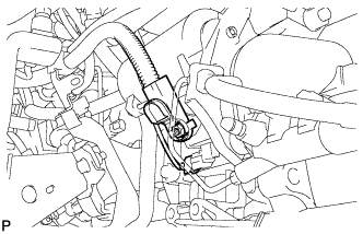 |
Disconnect the starter connector.
Remove the nut and disconnect the starter wire.
Remove the clutch release cylinder.
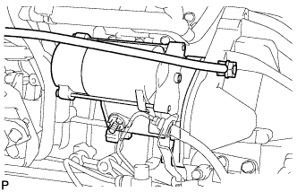 |
Remove the nut, bolt, ground cable and starter.
| 18. REMOVE FRONT EXHAUST PIPE ASSEMBLY |
Remove the 2 bolts and 2 compression springs.
Disconnect the front pipe from the outlet pipe and remove the gasket.
Remove the front pipe from the pipe support.
| 19. REMOVE PROPELLER SHAFT ASSEMBLY |
Front Side:
Remove the propeller shaft assembly (Click here).
Rear Side:
Remove the propeller shaft assembly (Click here).
| 20. REMOVE TRANSMISSION ASSEMBLY |
R151/R151F:
Remove the transmission assembly (Click here).
G50/G55:
Remove the transmission assembly (Click here).
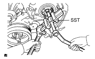
| 21. REMOVE FLYWHEEL SUB-ASSEMBLY |
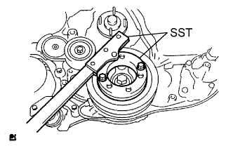 |
Using SST, hold the crankshaft.
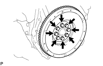 |
Remove the 8 bolts and flywheel.
| 22. REMOVE REAR END PLATE |
Remove the bolt and end plate.
| 23. REMOVE ENGINE ASSEMBLY |
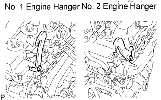 |
Set the No. 1 engine hanger and No. 2 engine hanger to the locations shown in the illustration.
| Parts Name | Parts No. |
| Engine hanger No. 1 | 12284-30020 |
| Bolt (91512-61014) | |
| Engine hanger No. 2 | 12282-67020 |
| Bolt (91642-81030) |
 |
Hold the engine with the engine sling device and chain block.
Remove the 4 bolts and 4 nuts.
Remove the engine by operating the engine sling device and chain block.
| 24. FIX ENGINE ON ENGINE STAND |
| 25. REMOVE NO. 1 TIMING BELT COVER |
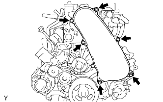 |
Remove the bolt and water hose clamp.
Remove the wire harness clamp.
Remove the 6 bolts and timing belt cover.
| 26. REMOVE TIMING BELT |
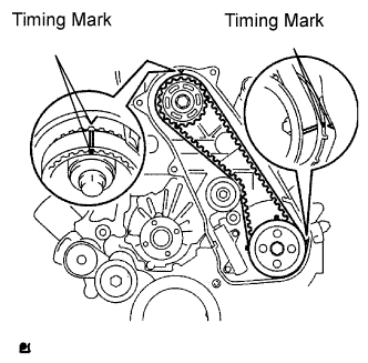 |
Turn the crankshaft clockwise and align the timing marks as shown in the illustration.
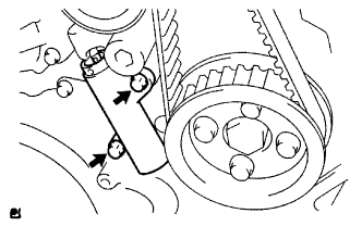 |
Uniformly loosen the 2 bolts and remove the timing belt tensioner.
Remove the timing belt.
Using a 10 mm hexagon wrench, remove the bolt, timing belt idler and washer.
| 27. REMOVE NO. 1 TIMING BELT TENSIONER ASSEMBLY |
| 28. REMOVE V-RIBBED BELT TENSIONER ASSEMBLY |
| 29. REMOVE GENERATOR BRACKET |
| 30. REMOVE GENERATOR ASSEMBLY |
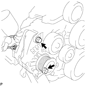 |
Remove the nut and generator wire.
Disconnect the generator connector.
Remove the 2 bolts, adjusting bar and generator.
| 31. REMOVE NO. 1 COMPRESSOR MOUNTING BRACKET |
Remove the 4 bolts and mounting bracket.
| 32. REMOVE MANIFOLD STAY |
 |
Remove the 2 bolts and stay.
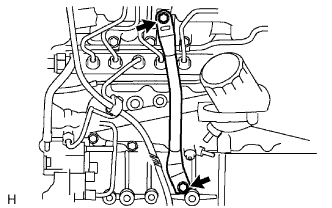
| 33. REMOVE FUEL INLET PIPE SUB-ASSEMBLY |
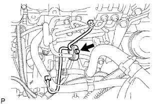 |
Remove the bolt and clamp.
Remove the 2 bolts and oil level gauge guide.
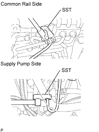 |
Using SST, loosen the union nuts and remove the fuel inlet pipe.
| 34. REMOVE INJECTION PIPE |
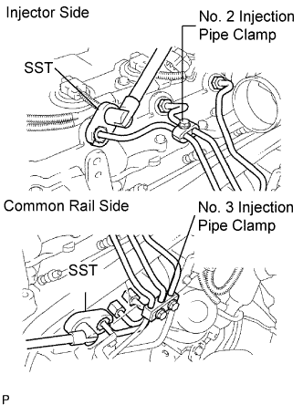 |
Remove the 2 nuts and No. 3 injection pipe clamp.
Remove the bolt and No. 2 injection pipe clamp.
Using SST, loosen the union nuts and remove the No. 1, No. 2 and No. 3 injection pipes.
 |
Remove the 2 bolts and disconnect the 2 injection pipe clamps.
 |
Using SST, loosen the union nuts and remove the No. 4 injection pipe.
| 35. REMOVE CYLINDER HEAD COVER SUB-ASSEMBLY |
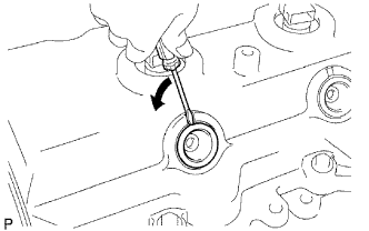 |
Using a small screwdriver, remove the holder seal by prying the portion between the holder seal and the cutout part of the cylinder head.
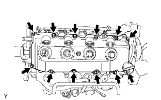 |
Remove the 10 bolts, 2 nuts, cylinder head cover and gasket.
| 36. REMOVE CAMSHAFT TIMING PULLEY |
 |
Remove the bolt of the camshaft timing pulley by holding the camshaft with a wrench.
Remove the camshaft timing pulley.
| 37. REMOVE NO. 1 TIMING BELT IDLER SUB-ASSEMBLY |
| 38. REMOVE NO. 2 TIMING BELT COVER |
Remove the 4 bolts, nuts and timing belt cover.
| 39. REMOVE WATER PUMP ASSEMBLY |
 |
Remove the 2 nuts, 6 bolts, water pump and gasket.
| 40. REMOVE VACUUM PUMP ASSEMBLY |
 |
Remove the vacuum hose.
Remove the 2 nuts, vacuum pump and 2 O-rings.
| 41. REMOVE VANE PUMP ASSEMBLY |
Remove the 2 nuts, vane pump and O-ring.
| 42. REMOVE PUMP DRIVE SHAFT PULLEY |
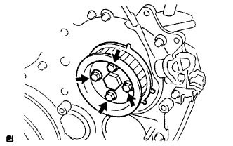 |
Remove the 4 bolts, No. 2 camshaft timing pulley flange and pump drive shaft pulley.
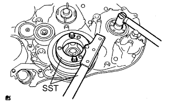 |
Using SST, hold the crankshaft pulley and remove the nut and O-ring.
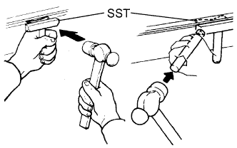
| 43. REMOVE CRANKSHAFT PULLEY |
 |
Using SST, remove the pulley bolt.
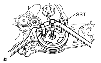 |
Using SST, remove the pulley.
| 44. REMOVE CAMSHAFT POSITION SENSOR |
Remove the bolt and sensor.
Remove the O-ring from the sensor.
| 45. REMOVE CRANKSHAFT POSITION SENSOR |
Remove the bolt and sensor.
Remove the O-ring from the sensor.
| 46. REMOVE TIMING GEAR COVER |
 |
Remove the wire harness clamp.
Remove the 14 bolts and 2 nuts.
Using a slotted screwdriver, gently separate the cover from the timing gear case.
Remove the cover and O-ring.
| 47. REMOVE NO. 1 IDLE GEAR |
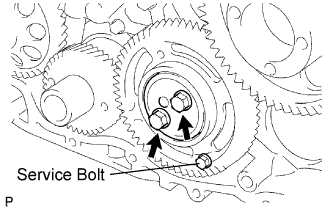 |
Secure the idle gears to the idle gear with the service bolt.
Remove the 2 bolts and thrust plate.
Turn the sub gear and align the gear teeth of the idle main gear and sub gear.
Remove the idle gear and sub gear.
Remove the idle gear shaft.
| 48. REMOVE CRANKSHAFT TIMING GEAR OR SPROCKET |
Remove the No. 1 crankshaft sensor plate.
Install the service bolt to the crankshaft.
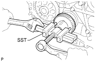 |
Using SST, remove the crankshaft timing gear.
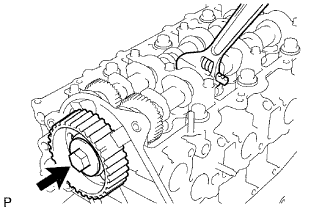
| 49. REMOVE INJECTION GEAR |
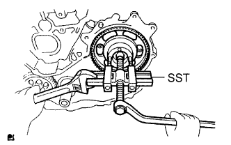 |
Using SST, remove the injection gear.
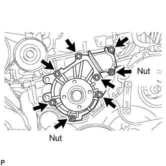
| 50. REMOVE FUEL SUPPLY PUMP ASSEMBLY |
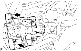
|
Remove the bolt and clamp.
Remove the 2 bolts and oil level gauge guide.
|
Using SST, loosen the union nuts and remove the fuel inlet pipe.
 |
Disconnect the 2 fuel hoses.
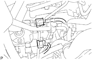 |
Disconnect the 2 connectors.
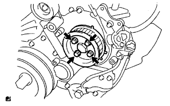 |
Remove the 4 bolts indicated by the arrows in the illustration.
Remove the No. 2 camshaft timing pulley flange and pump drive shaft pulley.
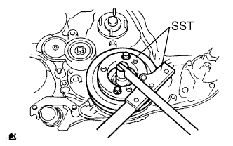
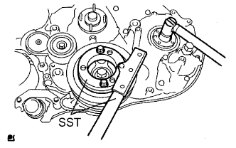 |
Remove the set nut and O-ring while holding the crankshaft pulley by using SST.
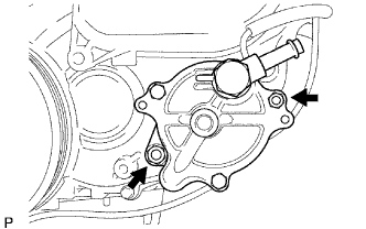
 |
Loosen the 2 nuts.
 |
Using SST, disconnect the pump from the injection gear.
Remove the 2 nuts and pump.
Remove the O-ring.
| 51. REMOVE OIL LEVEL GAUGE SUB-ASSEMBLY |
Remove the bolt and oil level gauge.
Remove the O-ring from the oil level gauge.
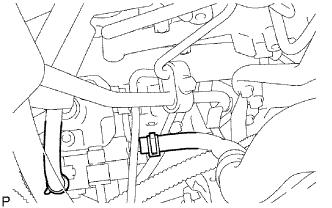
| 52. REMOVE OIL PAN SUB-ASSEMBLY |
Remove the 22 bolts and 2 nuts.
 |
Insert the blade of SST between the cylinder block and oil pan. Cut through the applied sealer and remove the oil pan.
Remove the oil pan gasket.
Remove the 2 bolts, nut, oil strainer and gasket.
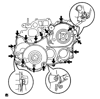
| 53. REMOVE TIMING GEAR CASE ASSEMBLY |
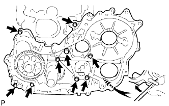 |
Remove the union bolt and 8 bolts.
Pry the gear case in the location shown in the illustration, and remove the gear case, driven rotor and gasket.
Remove the 2 O-rings.
