OIL PUMP > INSPECTION |
| 1. INSPECT OIL PUMP RELIEF VALVE |
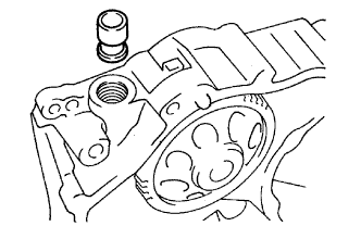 |
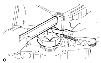
Coat the relief valve with engine oil and drop it into the relief vale hole.
Check that the relief valve falls in smoothly by its own weight.
If it does not, replace the relief valve. If necessary, replace the timing gear case.
| 2. INSPECT OIL PUMP ASSEMBLY |
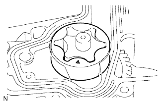 |
Install the driven rotor into the timing gear case with the mark facing the cylinder block side.
 |
Check the tip clearance.
Using a feeler gauge, measure the clearance between the drive and driven rotor tips.
| Specification | Clearance |
| Standard | 0.060 to 0.160 mm (0.0024 to 0.0063 in.) |
| Maximum | 0.21 mm (0.0083 in.) |
 |
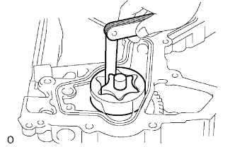
Check the body clearance.
Using a feeler gauge, measure the clearance between the oil pump body and drive rotor.
| Specification | Clearance |
| Standard | 0.100 to 0.170 mm (0.0039 to 0.0066 in.) |
| Maximum | 0.20 mm (0.0078 in.) |
 |
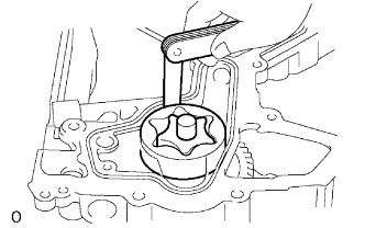
Check the side clearance.
Using a feeler gauge and precision straightedge, measure the clearance between the rotor and precision straightedge.
| Specification | Clearance |
| Standard | 0.030 to 0.090 mm (0.0012 to 0.0036 in.) |
| Maximum | 0.15 mm (0.0059 in.) |
