AIR FUEL RATIO SENSOR (for Sensor 1) > ON-VEHICLE INSPECTION |
| 1. INSPECT AIR FUEL RATIO SENSOR (for Sensor 1) |
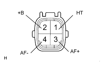 |
Using an ohmmeter, measure the resistance between the terminals.
| Tester Connection | Specified Condition |
| 1 (HT) - 2 (+B) | 1.8 to 3.4 Ω at 20°C (68°F) |
| 1 (HT) - 4 (AF-) | 10 kΩ or higher |
| 2. INSPECT AIR FUEL RATIO COMPENSATION SYSTEM |
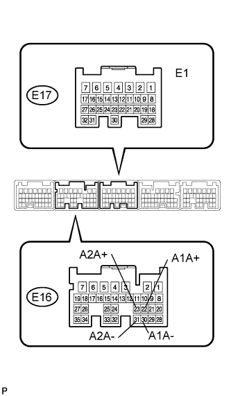 |
Measure the voltage between terminals of the ECM.
| Tester Connection | Condition | Specified Condition |
| E16-22 (A1A+) - E17-1 (E1) | Ignition switch ON | 3.3 V |
| E16-22 (A1A+) - E17-1 (E1) | Ignition switch ON | 3.0 V |
| E16-22 (A1A+) - E17-1 (E1) | Ignition switch ON | 3.3 V |
| E16-22 (A1A+) - E17-1 (E1) | Ignition switch ON | 3.0 V |
Connect the intelligent tester to the DLC3.
Select "DATA MONITOR" - "A/FS B1 S1", "A/FS B2 S1" and "O2S B1 S2" to display the monitor.
Warm up the A/F sensor with the engine speed at 2,500 rpm for approximately 2 minutes.
 |
Keep the engine speed at 2,500 rpm and confirm that the displays of "A/FS B1S1" and "A/FS B2 S1" are similar to the illustration.
Confirm that the display of "O2S B1 S2" changes between 0 to 1 V with the engine speed at 2,500 rpm.
