VENTILATION VALVE > INSTALLATION |
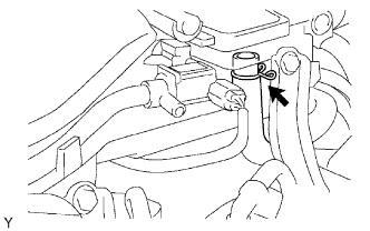
| 1. INSTALL VENTILATION VALVE SUB-ASSEMBLY |
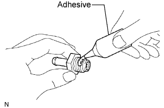 |
Apply adhesive to 2 or 3 threads of the valve.
 |
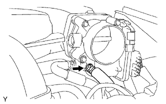
Install the valve.
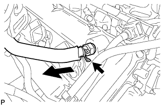
Connect the ventilation hose to the valve.
Secure the hose with the clamp.
| 2. INSTALL INTAKE AIR SURGE TANK |
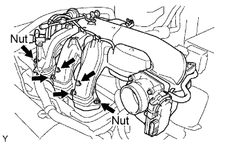 |
Install a new gasket and the surge tank with the 2 nuts.
Using an 8 hexagon wrench, install the 4 bolts.
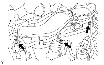 |
Install the 3 upper bolts which are used to secure the 2 surge tank stays and throttle body bracket.
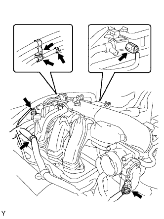 |
Install the 3 wire harness clamps and hose clamp.
Connect the throttle motor connector.
Connect the 2 VSV connectors.
 |
Connect the ventilation hose.
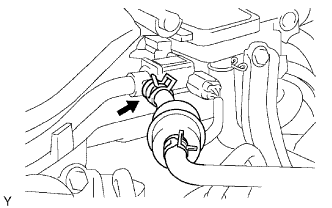 |
Connect the vapor feed hose assembly.
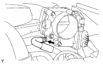 |
Connect the No. 4 water by-pass hose.
 |
Connect the No. 5 water by-pass hose.
| 3. INSTALL V-BANK COVER |
Install the cover with the 2 nuts.
| 4. CONNECT CABLE TO NEGATIVE BATTERY TERMINAL |
| 5. PERFORM INITIALIZATION |
Perform initialization (Click here).
