FUEL INJECTOR > INSTALLATION |
| 1. INSTALL INJECTOR ASSEMBLY |
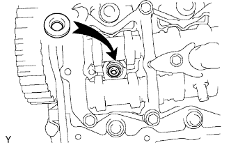 |
Install 4 new injection nozzle sheets to the cylinder head.
Apply a light amount of clean engine oil to 4 new O-rings.
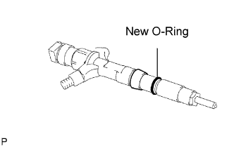 |
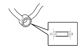
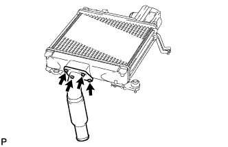
Install the O-ring to each injector as shown in the illustration.
Insert the 4 injectors into the cylinder head.
Register injector compensation code (when replacing with a new injector).
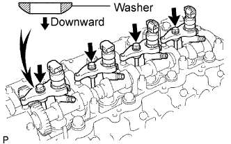 |
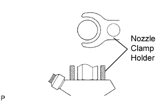
Temporarily install 4 new washers and the 4 nozzle clamps with the 4 clamp bolts.
Temporarily install the 4 injection pipes with the union nuts.
 |
Check the nozzle leakage pipe. Check that there are no scratches or dents on the 5 union seal surfaces.
If scratches or dents are present, replace the nozzle leakage pipe.
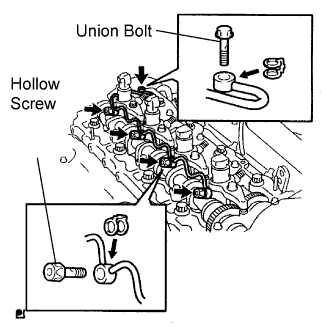 |
Set the leakage pipe and 5 new gaskets in place.
Apply a light amount of oil to the 4 hollow screws and union bolt.
 |
Temporarily install the leakage pipe with the 4 hollow screws and union bolt.
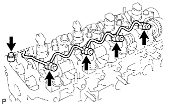
Tighten the 4 holder clamp bolts.
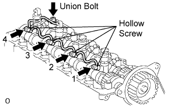 |
Tighten the 4 hollow screws in order from 1 to 4.
Tighten the union bolt.
Remove the 4 injection pipes.
| 2. CHECK FOR FUEL LEAKS |
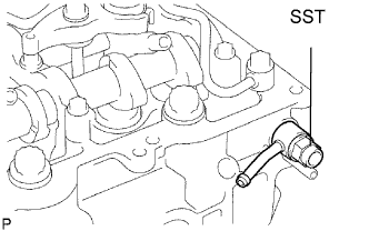 |
Check that there are no leaks from the nozzle leakage pipe connection.
Install the gasket and No. 2 nozzle leakage pipe to the cylinder head with SST (check valve).
Apply a light amount of soapy water (or other fluid for detecting fuel leakage) on the nozzle leakage pipe connection.
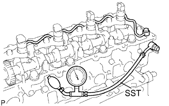 |
Install SST (turbocharger pressure gauge) to the fuel return side of the leakage pipe, and maintain 250 kPa (2.5 kgf/cm2, 35.5 psi) of pressure for 60 seconds to check that no bubbles form.
After checking for fuel leaks, wipe off the soapy water from the leakage pipe connection.
Remove SST, No. 2 nozzle leakage pipe and gasket.
| 3. INSTALL CYLINDER HEAD COVER SUB-ASSEMBLY |
Remove any old seal packing (FIPG) material from the cylinder head.
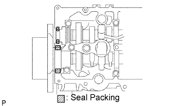 |
Apply seal packing to the specific areas shown in the illustration.
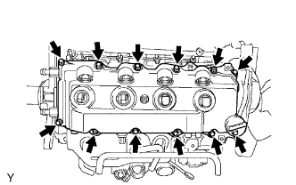 |
Install the gasket and cylinder head cover with the 10 bolts and 2 nuts.
Install 4 new nozzle holder seals.
| 4. INSTALL INJECTION PIPE |
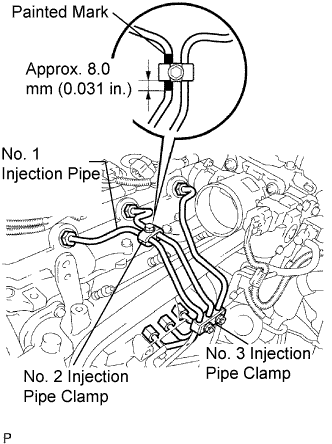 |
Temporarily install the No. 1, No. 2 and No. 3 injection pipes with the union nuts.
Install the No. 2 and No. 3 injection pipe clamps with the bolt and 2 nuts, as shown in the illustration.
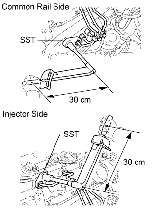 |
Using SST, tighten the injection pipe union nuts on the common rail side.
Using SST, tighten the injection pipe union nuts on the injector side.
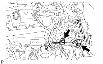 |
Temporarily install the No. 4 injection pipe with the union nuts.
Install 2 new injection pipe clamps with the 2 bolts.
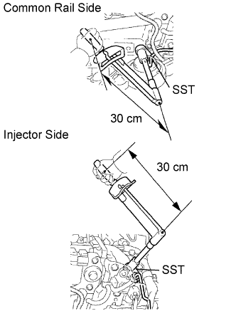 |
Using SST, tighten the injection pipe union nuts on the common rail side.
Using SST, tighten the injection pipe union nuts on the injector side.
| 5. INSTALL CHARGE AIR COOLER ASSEMBLY WITH INTAKE AIR CONNECTOR |
 |
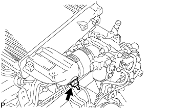
Install a new gasket and the intake air connector with the 4 bolts.
 |
Using a 22 mm deep socket wrench, install a new gasket and the IAT sensor.
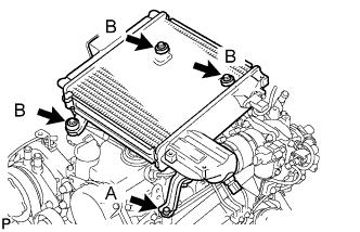 |
Install the CAC with the 4 bolts.
Tighten the 4 hose clamps of the No. 1 and No. 2 air hose.
Connect the diesel turbo IAT sensor connector.
| 6. INSTALL NO. 1 ENGINE COVER SUB-ASSEMBLY |
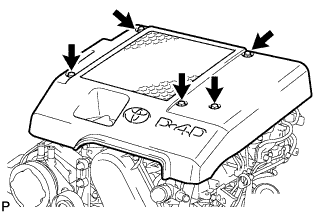 |
Install the cover with the 3 bolts and 2 nuts.
| 7. ADD FUEL |
| 8. TIGHTEN FUEL TANK CAP ASSEMBLY |
| 9. BLEED AIR FROM FUEL SYSTEM |
 |
Using the hand pump, bleed air from the fuel system until pumping becomes difficult.
| 10. CONNECT CABLE TO NEGATIVE BATTERY TERMINAL |
| 11. PERFORM INITIALIZATION |
Perform initialization (Click here).
| 12. REGISTER INJECTOR COMPENSATION CODE |
Register the injector compensation code (Click here).
| 13. CHECK FOR FUEL LEAKS |
| 14. CHECK FOR OIL LEAKS |
