FUEL INJECTOR > INSTALLATION |
| 1. INSTALL INJECTOR ASSEMBLY |
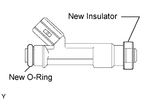 |
Install a new insulator to each fuel injector.
Apply a light coat of spindle oil or gasoline to a new O-ring and install it to each fuel injector.
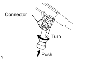 |
While turning the fuel injector left and right, install it to the fuel delivery pipe.
Position the fuel injector connector outward.
| 2. INSTALL FUEL DELIVERY PIPE SUB-ASSEMBLY |
 |
Place the fuel delivery pipe together with the 6 fuel injectors on the intake manifold.
Temporarily install the 6 bolts which are used to hold the fuel delivery pipe to the intake manifold.
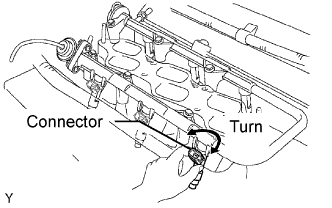
Check that the fuel injectors rotate smoothly.
Position the fuel injector connector outward.
Tighten the 6 bolts which are used to hold the fuel delivery pipe to the intake manifold.
Connect the 6 fuel injector connectors.
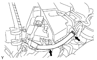
| 3. CONNECT NO. 2 FUEL PIPE SUB-ASSEMBLY |
Connect the fuel pipe.
 |
Check that there is no damage or contamination in the connected part of the pipe.
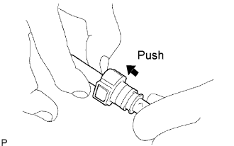
Align the axis of the connector with the axis of the pipe. Push the pipe into the connector until the connector makes a "click" sound. If the connection is tight, apply a little amount of fresh engine oil on the tip of the pipe.
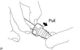 |
After having finished the connection, try to pull apart the pipe and the connector and confirm that they are securely connected.
Install the fuel pipe clamp.
| 4. CONNECT NO. 1 FUEL PIPE SUB-ASSEMBLY |
Connect the fuel pipe.
|
Check that there is no damage or contamination in the connected part of the pipe.
Align the axis of the connector with the axis of the pipe. Push the pipe into the connector until the connector makes a "click" sound. If the connection is tight, apply a little amount of fresh engine oil on the tip of the pipe.
|
After having finished the connection, try to pull apart the pipe and the connector and confirm that they are securely connected.
Install the fuel pipe clamp.
| 5. INSTALL INTAKE AIR SURGE TANK |
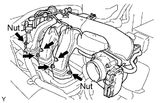 |
Install a new gasket and the surge tank with the 2 nuts.
Using an 8 hexagon wrench, install the 4 bolts.
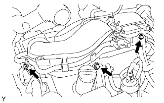 |
Install the 3 upper bolts which are used to secure the 2 surge tank stays and throttle body bracket.
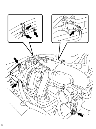 |
Install the 3 wire harness clamps and hose clamp.
Connect the throttle motor connector.
Connect the 2 VSV connectors.
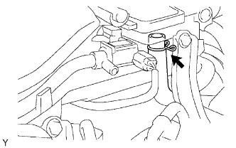 |
Connect the ventilation hose.
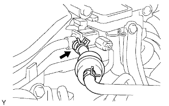 |
Connect the vapor feed hose assembly.
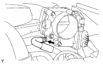 |
Connect the No. 4 water by-pass hose.
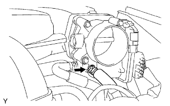 |
Connect the No. 5 water by-pass hose.
| 6. INSTALL AIR CLEANER ASSEMBLY |
| 7. CONNECT NO. 2 VENTILATION HOSE |
 |
| 8. INSTALL V-BANK COVER |
Install the cover with the 2 nuts.
| 9. ADD ENGINE COOLANT |
Tighten all the plugs and fill the radiator with TOYOTA Super Long Life Coolant (SLLC).
| Item | Specified Condition |
| A/T | 9.8 liters (10.4 US qts, 8.6 lmp. qts) |
| M/T | 8.5 liters (9.0 US qts, 7.5 lmp. qts) |
Press the inlet and outlet radiator hoses several times by hand, and then check the level of the coolant.
Install the radiator cap.
Bleed air from the cooling system.
Warm up the engine until the thermostat opens. While the thermostat is open, circulate the coolant for several minutes.
Maintain the engine speed at 2,000 to 2,500 rpm.
Press the inlet and outlet radiator hoses several times by hand to bleed air.
Stop the engine and wait until the coolant cools down to ambient temperature.
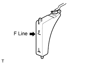 |
Check the coolant level in the radiator reservoir.
If the coolant level is low, add SLLC to the reservoir F line.
| 10. CONNECT CABLE TO BATTERY NEGATIVE TERMINAL |
| 11. PERFORM INITIALIZATION |
Perform initialization (Click here).
| 12. CHECK FOR FUEL LEAKS |
Connect the intelligent tester to the DLC3.
Turn the ignition switch ON.
Push the intelligent tester main switch ON.
Select Active Test and enter the following menus: Powertrain / Engine and ECT / Active Test / Control the Fuel Pump / Speed.
Check for fuel leaks.
Check that there are no fuel leaks after performing maintenance anywhere on the fuel system.
