WINDOW DEFOGGER SYSTEM > INSPECTION |
| 1. INSPECT REAR WINDOW DEFOGGER SWITCH ASSEMBLY |
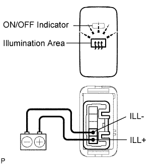 |
Check the illumination area of the switch.
| Measurement Condition | Specified Condition |
| Battery positive (+) 1 (ILL+) Battery negative (-) 2 (ILL-) | Illuminates |
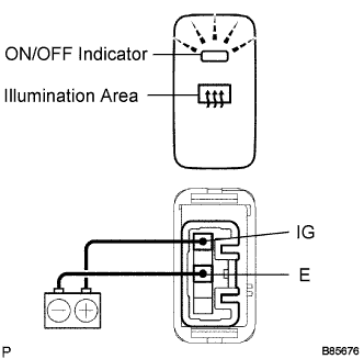 |
Check the ON/OFF indicator of the switch.
Push the switch several times. Check that the ON/OFF indicator illuminates or turns off according to switch operation.
| Measurement Condition | Switch Condition | Specified Condition |
| Battery positive (+) 5 (IG) Battery negative (-) 3 (E) | Defogger switch ON | Illuminates |
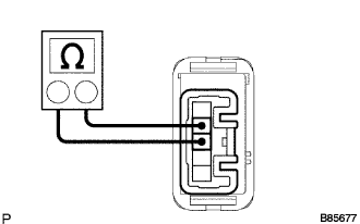 |
Measure the resistance of the switch.
| Tester Connection | Switch Condition | Specified Condition |
| 4 (D) - 3 (E) | ON | Below 1 Ω |
| 4 (D) - 3 (E) | OFF | 10 k Ω or higher |
| 2. INSPECT REAR WINDOW DEFOGGER WIRE |
 |
Turn the ignition switch ON.
Turn the defogger switch ON.
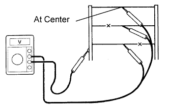  |
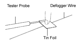
Measure the voltage at the center of each defogger wire as shown in the illustration.
| Voltage | Criteria |
| Approx. 5 V | Wire is not broken |
| Approx. 10 or 0 V | Wire is broken |
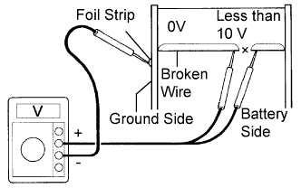
Place the voltmeter's positive (+) lead against the defogger wire on the battery side.
Place the voltmeter's negative (-) lead with the foil strip against the wire on the ground side.
Slide the positive (+) lead from the battery side to the ground side.
The point where the voltage jumps from approximately 10 V to 0 V is where the defogger wire is broken.
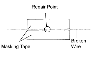 |
If necessary, repair the defogger wire.
Clean the broken wire tips with grease, wax and silicone remover.
Place the masking tape along both sides of the wire.
Thoroughly mix the repair agent (Dupont paste No. 4817 or equivalent).
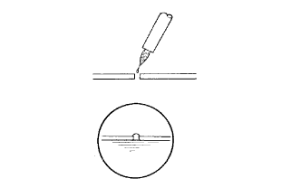 |
Using a fine tip brush, apply a small amount of the agent to the wire.
After a few minutes, remove the masking tape.
| 3. INSPECT RELAY (Marking: DEF) |
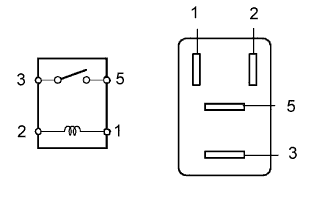 |
Measure the resistance of the DEF relay.
| Tester Condition | Specified Condition |
| 3 - 5 | 10 kΩor higher |
| 3 - 5 | Below 1Ω (when battery voltage is applied to terminals 1 and 2) |
