ENGINE UNIT > REASSEMBLY |
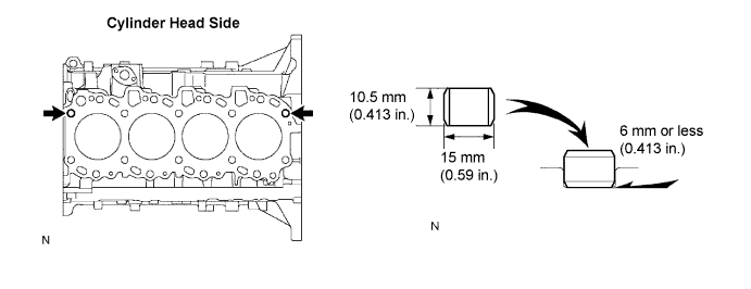
| 1. INSTALL TIGHT PLUG |
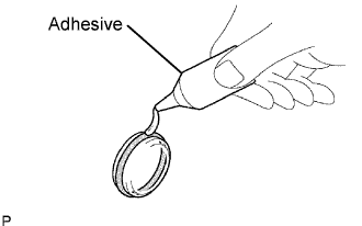 |
Apply adhesive to the end of a new tight plug.
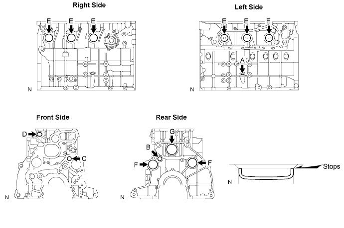
Position A:
Using a 14 mm steel bar and hammer, tap in the tight plug as shown in the illustration.
Other Positions:
Using SST and a hammer, tap in a new tight plug as shown in the illustration.
Position B
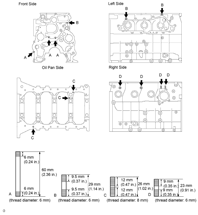
| 2. INSTALL STUD BOLT |
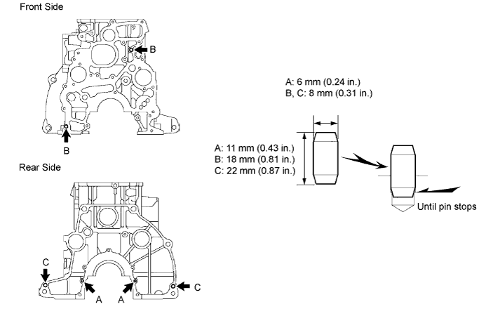
| 3. INSTALL STRAIGHT PIN |
| 4. INSTALL RING PIN |
| 5. INSTALL NO. 1 STRAIGHT SCREW PLUG |
Install a new gasket and the screw plug.
| 6. INSTALL NO. 1 OIL NOZZLE SUB-ASSEMBLY |
 |
Align the pin of the oil nozzle with the pin hole of the cylinder block.
Install the oil nozzle with the check valve. Install the 4 oil nozzles and check valves.
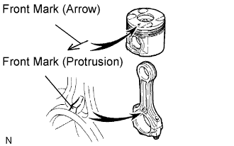
| 7. INSTALL PISTON PIN |
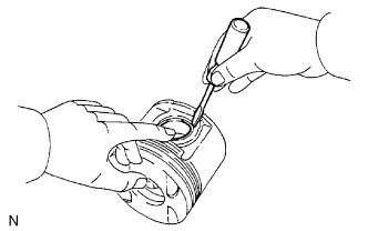 |
Assemble the piston and connecting rod.
Using a small screwdriver, install a new snap ring on one side of the piston pin hole.
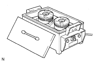 |
Gradually heat the piston to about 80°C (176°F).
 |
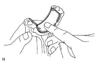
Coat the piston pin with engine oil.
Align the front marks of the piston and connecting rod, and push in the piston pin with your thumb.
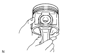 |
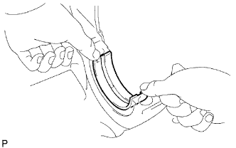
Check fit between the piston and piston pin. Try to move the piston back and forth on the piston pin.
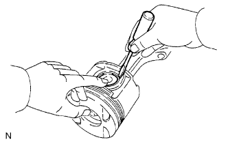 |
Using a small screwdriver, install a new snap ring on the other side of the piston pin hole.
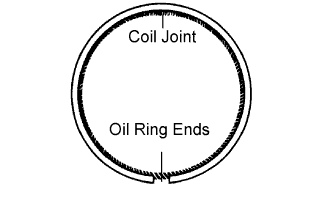 |
Install the piston rings.
Install the coil and oil ring by hand.
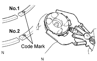 |
Using a piston ring expander, install the No. 1 and No. 2 piston rings with the code mark facing upward.
| Number | Mark |
| No. 1 | NP |
| No. 2 | N |
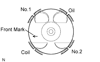 |
Position the piston rings so that the ring ends are as shown.
| 8. INSTALL CONNECTING ROD BEARING |
 |
Align the bearing claw with the groove of the connecting rod or connecting cap.
Install the bearings in the connecting rod and connecting rod cap.
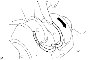
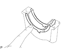
| 9. INSTALL CRANKSHAFT BEARING |
 |
Align the bearing claw with the claw groove of the cylinder block, and push in the 5 upper bearings.
Align the bearing claw with the claw groove of the crankshaft bearing cap, and push in the 5 lower bearings.
| 10. INSTALL CRANKSHAFT |
 |
Place the crankshaft on the cylinder block.
Install the 2 upper thrust washers to the No. 5 journal position of the cylinder block.
Push the crankshaft toward the front (rear) side.
Install the 2 thrust washers with the oil grooves facing outward.
 |
Install the 2 thrust washers on the No. 5 bearing cap with the grooves facing outward.
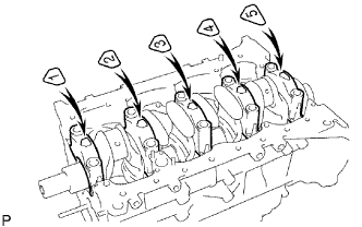 |
Install the 5 crankshaft bearing caps in their proper locations.
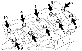 |
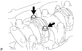
Install the crankshaft bearing cap bolts.
Apply a light coat of the engine oil on the threads and under the bolt heads of the main bearing caps.
Install and uniformly tighten the 10 bolts of the main bearing caps in several passes in the sequence shown in the illustration.
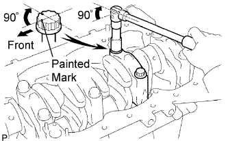 |
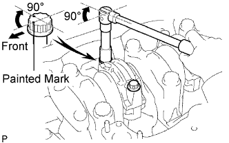
Mark the front of the main bearing cap bolt with paint.
Retighten the main bearing cap bolts 90° in the numerical order shown above.
Check that the painted mark is now at a 90° angle to the front.
Check that the crankshaft turns smoothly.
Check the crankshaft thrust clearance.
| 11. INSTALL PISTON AND CONNECTING ROD |
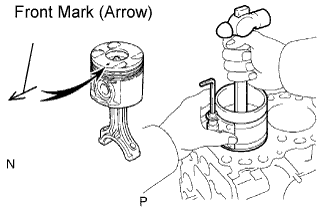 |
Using a piston ring compressor, push the correctly numbered piston and connecting rod assembly into the cylinder with the front mark of the piston facing forward.
 |
Place the connecting rod cap on the connecting rod.
Match the numbered connecting rod cap with the connecting rod.
Align the pins of the connecting rod cap with the pin holes of the connecting rod, and install the connecting rod cap.
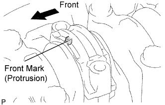 |
Check that the front mark of the connecting rod cap is facing forward.
 |
Install the connecting rod cap bolts.
Apply a light of engine oil on the threads and under the heads of the connecting rod cap bolts.
Install and alternately tighten the bolts of the connecting rod cap in several passes.
 |
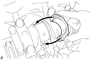
Mark the front of the connecting rod cap bolts with paint.
Retighten the connecting rod cap bolts 90° as shown.
Check that the painted mark is now at a 90° angle to the front.
Check that the crankshaft turns smoothly.
Check the connecting rod thrust clearance (Click here).
| 12. INSTALL CYLINDER BLOCK OIL ORIFICE |
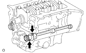
| 13. INSTALL SUPPLY PUMP GEAR BEARING |
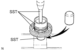 |
Using SST and a press, press in a new bearing.
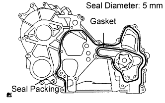
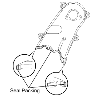
| 14. INSTALL REAR ENGINE OIL SEAL RETAINER |
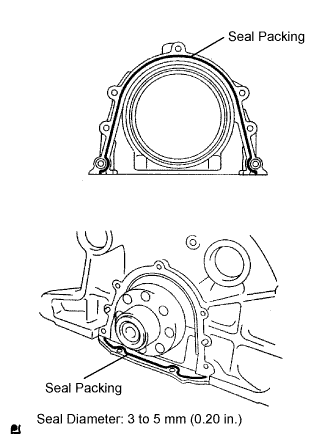 |
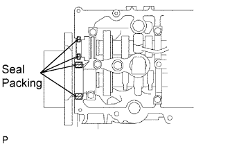
Remove any old packing (FIPG) material.
Remove oil seal packing (FIPG) from oil pan and cylinder block.
Apply seal packing to the specific places described in the illustration.
 |
Install the retainer with the 7 bolts. Alternately tighten the 7 bolts in several passes.
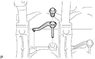
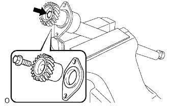
| 15. INSTALL NO. 2 BALANCE SHAFT DRIVEN GEAR |
 |
Mount the balance shaft between aluminium plates in a vise.
Align the balance shaft knock pin with the knock pin hole. Then install the balance shaft thrust washer and balance shaft driven gear.
Install the bolt.
| 16. INSTALL NO. 2 BALANCE SHAFT SUB-ASSEMBLY |
 |
Install the balance shaft with the 2 bolts.
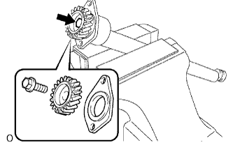
| 17. INSTALL NO. 1 BALANCE SHAFT DRIVEN GEAR |
 |
Mount the balance shaft between aluminium plates in a vise.
Align the balance shaft knock pin with the knock pin hole. Then install the balance shaft thrust washer and balance shaft driven gear.
Install the bolt.
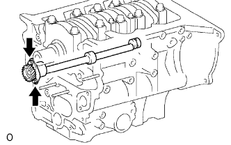
| 18. INSTALL NO. 1 BALANCE SHAFT SUB-ASSEMBLY |
 |
Install the balance shaft with the 2 bolts.
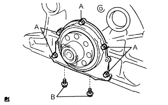
| 19. INSTALL TIMING GEAR CASE ASSEMBLY |
Remove any old packing (FIPG) material.
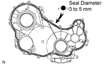
 |
Apply seal packing to the timing gear case as shown in the illustration.
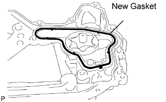 |
Install a new gasket to the groove of the timing gear case.
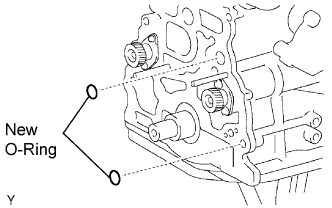 |
Install 2 new O-rings to the cylinder block groove of the timing gear case.
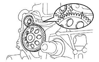 |
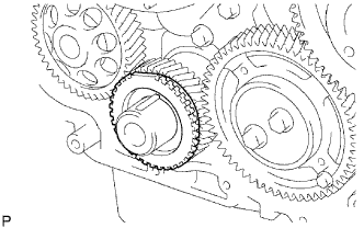
Align the "2" marks of the balance shaft driven gear No. 1 and oil pump drive gear.
Align the mark on the oil pump drive gear with the mark on the timing gear case.
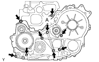 |
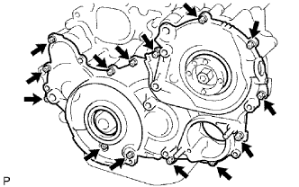
Install the timing gear case with the union bolt and 8 bolts.
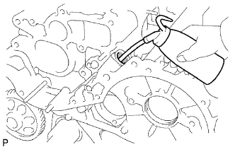 |
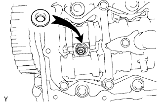
Remove the screw plug.
Pour in approx. 20 cc (0.12 cu in.) of engine oil into the oil pump.
Reinstall a new gasket and the screw plug.
| 20. INSTALL OIL STRAINER SUB-ASSEMBLY |
Install a new gasket and the oil strainer with the 2 bolts and nut.
| 21. INSTALL OIL PAN SUB-ASSEMBLY |
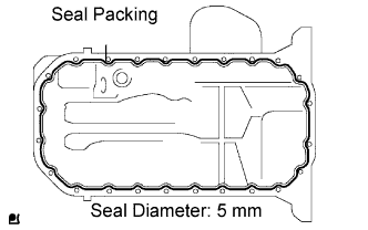 |
Remove any old packing (FIPG) material.
Apply seal packing to the oil pan as shown in the illustration.
Install the oil pan with the 22 bolts and 2 nuts.
Install the oil level gauge sensor with the 4 bolts.
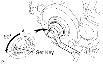
| 22. INSTALL CRANKSHAFT TIMING GEAR OR SPROCKET |
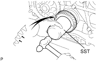 |
Face the crankshaft timing gear with timing mark 1 facing the forward.
Align the set key on the crankshaft with the key groove of the crankshaft timing gear.
Using SST and a hammer, tap in the timing gear.
| 23. INSTALL SUPPLY PUMP GEAR |
Install the supply pump with the 2 nuts.
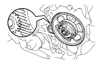 |
Align the "3" marks of the balance shaft driven gear No. 2 and supply pump gear.
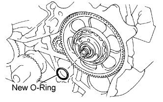 |
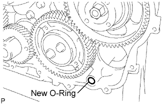
Install a new O-ring to the supply pump gear.
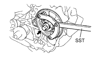 |
Install the supply pump gear set nut.
Using SST, tighten the nut.
| 24. INSTALL NO. 2 IDLE SUB GEAR |
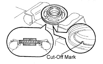 |
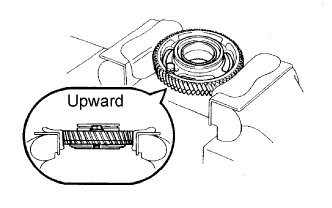
Mount the No.1 idle gear in a vise.
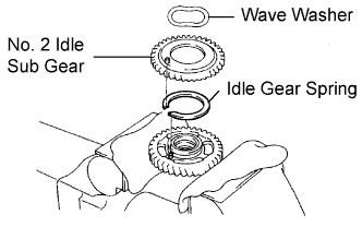 |
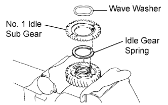
Install the idle gear spring.
Install the No. 2 idle sub-gear.
Install the wave washer.
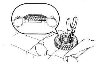 |
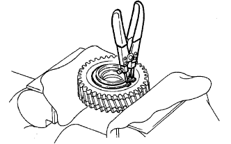
Using snap ring pliers, install the snap ring.
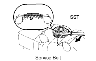 |
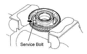
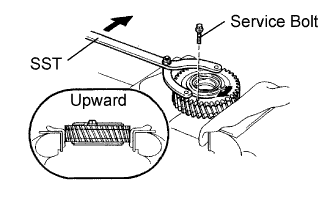
Using SST, align the holes of the No. 1 idle gear and No. 2 idle sub gear by turning the No.2 idle sub gear clockwise, and install a service bolt.
Remove the No. 1 idle gear from the vise and turn it upside down.
| 25. INSTALL NO. 1 IDLE SUB GEAR |
 |
Mount the No. 1 idle gear and No. 2 idle sub gear in a vise.
 |
Remove the service bolt.
 |
Install the idle gear spring.
Install the No. 1 idle sub gear.
Install the wave washer.
 |
Using a snap ring pliers, install the snap ring.
 |
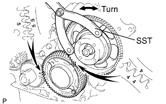
Using SST, align the holes of the No. 1 idler gear and No. 1 idle sub gear by turning the No. 1 idle sub gear clockwise, and install a service bolt.
| 26. INSTALL NO. 1 IDLE GEAR |
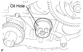 |
Install the gear shaft as shown in the illustration.
 |
Align the "5" timing marks of the idle gear and crankshaft timing gear.
Using SST, turn the supply pump gear, and align the "4" timing marks of the idle gear and supply pump gear, and mesh the gears.
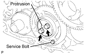 |
Face the thrust plate with the protrusion facing the forward.
Align the bolt holes, and install the thrust plate with the 2 bolts.
Remove the service bolt.
| 27. INSTALL NO. 1 CRANKSHAFT POSITION SENSOR PLATE |
 |
Align the set key with the key groove of the sensor plate.
Install the sensor plate, facing the cup side outward.
| 28. INSTALL TIMING GEAR CASE ASSEMBLY |
Remove any old packing (FIPG) material.
 |
Apply seal packing to the timing gear cover as shown in the illustration.
 |
Install a new O-ring to the timing gear case.
 |
Install the timing gear cover with the 14 bolts and 2 nuts.
| 29. INSTALL WATER PUMP ASSEMBLY |
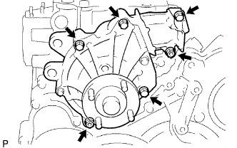 |
Install a new gasket and the water pump with the 5 bolts and 2 nuts.
| 30. INSTALL CYLINDER HEAD SUB-ASSEMBLY |
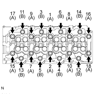 |
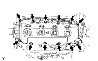
Apply a light coat of engine oil on the threads and under the heads of the cylinder head bolts.
Install and uniformly tighten the 18 cylinder head bolts, in several passes in the sequence shown in the illustration.
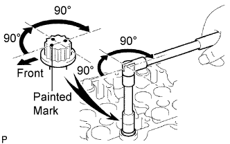 |
Mark the front of the cylinder head bolt with paint.
Further tighten the cylinder head bolts by 90° in the sequence shown in the illustration above.
Finally, tighten the cylinder head bolts by an additional 90°.
Check that the painted mark is now facing rearward.
| 31. INSTALL CAMSHAFT |
 |
Using the crankshaft pulley bolt, set the No. 1 cylinder to 90° BTDC/compression.
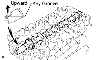 |
Install the camshaft.
Apply MP grease to the thrust portion of the camshaft.
Place the camshaft on the cylinder head, facing the key groove upward.
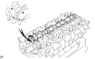 |
Align the timing marks (1 dot mark) of the camshaft drive and driven main gears, and set the No. 2 camshaft in place.
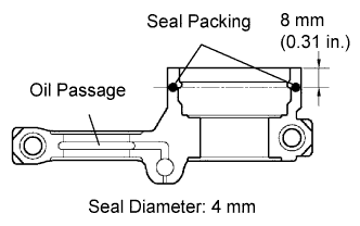 |
Remove any old packing (FIPG) material from the camshaft bearing cap.
Apply seal packing to the specified areas shown in the illustration.
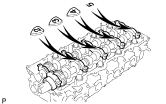 |
Install the 5 bearing caps in their proper locations.
 |
Apply a light coat of engine oil on the threads and under the heads of the bearing cap bolts.
Install and uniformly tighten the 10 bearing cap bolts in several passes in the sequence shown in the illustration.
Install the camshaft oil seal.
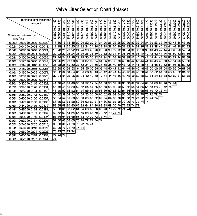
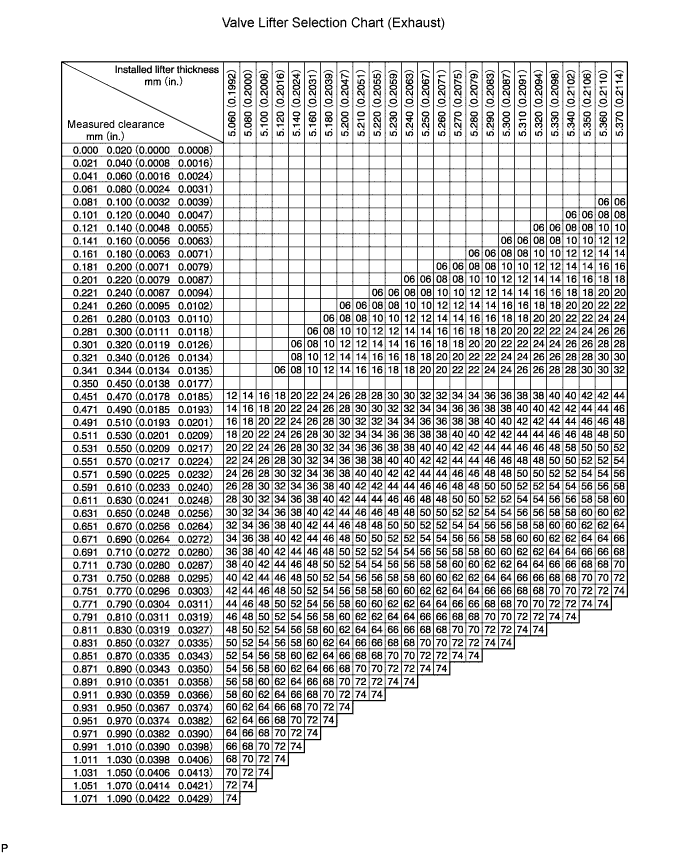
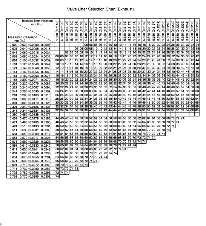
| 32. INSPECT VALVE CLEARANCE |
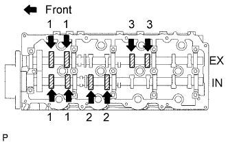 |
Check only the valves indicated.
Using a feeler gauge, measure the clearance between the valve lifter and camshaft.
| Intake | Exhaust |
| 0.20 to 0.30 mm (0.008 to 0.012 in.) | 0.35 to 0.45 mm (0.014 to 0.018 in.) |
Turn the crankshaft 360° to set the No. 4 cylinder to TDC / compression.
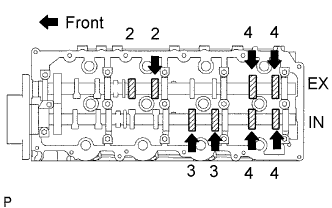 |
Check only the valves indicated.
Using a feeler gauge, measure the clearance between the valve lifter and camshaft.
| Intake | Exhaust |
| 0.20 to 0.30 mm (0.008 to 0.012 in.) | 0.35 to 0.45 mm (0.014 to 0.018 in.) |
| 33. ADJUST VALVE CLEARANCE |
Drain coolant.
Remove the fan shroud.
Remove the No. 1 timing belt cover.
Remove the timing belt.
Remove the camshaft timing pulley.
Remove the No. 1 timing belt idler.
Remove the No. 2 timing belt cover.
Remove the camshafts.
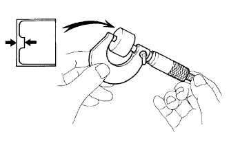 |
Remove the valve lifters.
Using a micrometer, measure the thickness of the removed lifter.
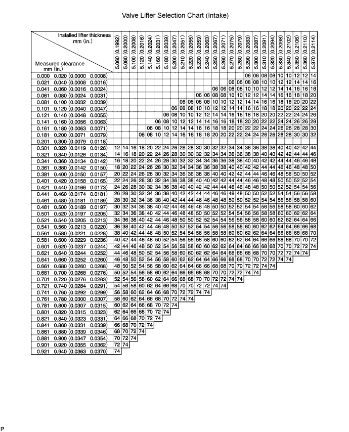
Calculate the thickness of a new lifter so that the valve clearance comes within the specified value.
| A | B | C |
| Thickness of new lifter | Thickness of used lifter | Measured valve clearance |
Select a new lifter with a thickness as close as possible to the calculated values.
Install the selected valve lifter.
| Shim No. | Thickness | Shim No. | Thickness | Shim No. | Thickness |
| 06 | 5.060 (0.1992) | 30 | 5.300 (0.2087) | 54 | 5.540 (0.2181) |
| 08 | 5.080 (0.2000) | 32 | 5.320 (0.2094) | 56 | 5.560 (0.2189) |
| 10 | 5.100 (0.2008) | 34 | 5.340 (0.2102) | 58 | 5.580 (0.2197) |
| 12 | 5.120 (0.2016) | 36 | 5.360 (0.2110) | 60 | 5.600 (0.2205) |
| 14 | 5.140 (0.2024) | 38 | 5.380 (0.2118) | 62 | 5.620 (0.2213) |
| 16 | 5.160 (0.2031) | 40 | 5.400 (0.2126) | 64 | 5.640 (0.2220) |
| 18 | 5.180 (0.2039) | 42 | 5.420 (0.2134) | 66 | 5.660 (0.2228) |
| 20 | 5.200 (0.2047) | 44 | 5.440 (0.2142) | 68 | 5.680 (0.2236) |
| 22 | 5.220 (0.2055) | 46 | 5.460 (0.2150) | 70 | 5.700 (0.2244) |
| 24 | 5.240 (0.2063) | 48 | 5.480 (0.2157) | 72 | 5.720 (0.2252) |
| 26 | 5.260 (0.2071) | 50 | 5.500 (0.2165) | 74 | 5.740 (0.2260) |
| 28 | 5.280 (0.2079) | 52 | 5.520 (0.2173) | - | - |
Install the camshaft.
Install the No. 2 timing belt cover.
Install the No. 1 timing belt idler.
Install the camshaft timing pulley.
Install the timing belt.
Install the No. 1 timing belt cover.
Install the fan shroud.
Add engine coolant.
| 34. INSTALL NO. 2 TIMING BELT COVER |
 |
Apply seal packing (FIPG) to the specified areas shown in the illustration.
Install the No. 2 timing belt cover with the 4 bolts and nut.
| 35. INSTALL CAMSHAFT TIMING PULLEY |
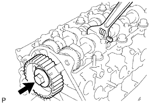 |
Install the camshaft timing pulley.
Fasten the bolt of the camshaft timing pulley by holding the camshaft with a wrench.
| 36. INSTALL INJECTOR ASSEMBLY |
 |
Install 4 new injection nozzle sheets to the cylinder head.
Apply a light amount of clean engine oil to 4 new O-rings.
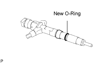 |
Install the O-ring to each injector as shown in the illustration.
Insert the 4 injectors into the cylinder head.
Register injector compensation code (when replacing with a new injector).
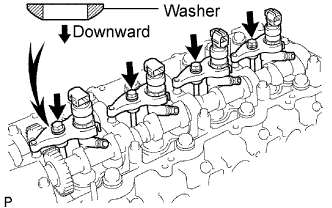 |
Temporarily install 4 new washers and the 4 nozzle clamps with the 4 clamp bolts.
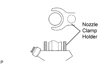
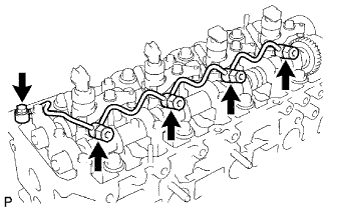
Temporarily install the 4 injection pipes with the union nuts.
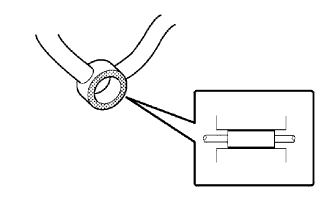 |
Check the nozzle leakage pipe. Check that there are no scratches or dents on the 5 union seal surfaces.
If scratches or dents are present, replace the nozzle leakage pipe.
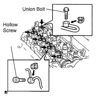 |
Set the leakage pipe and 5 new gaskets in place.
Apply a light amount of oil to the 4 hollow screws and union bolt.
 |
Temporarily install the leakage pipe with the 4 hollow screws and union bolt.
Tighten the 4 holder clamp bolts.
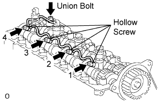 |
Tighten the 4 hollow screws in order from 1 to 4.
Tighten the union bolt.
Remove the 4 injection pipes.
| 37. INSTALL CYLINDER HEAD COVER SUB-ASSEMBLY |
 |
Remove any old seal packing (FIPG) material from the cylinder head.
Apply seal packing to the specific areas shown in the illustration.
 |
Install the gasket and cylinder head cover with the 10 bolts and 2 nuts.
Install 4 new nozzle holder seals.
| 38. INSTALL NOZZLE HOLDER SEAL |
Install 4 new holder seals.
| 39. INSTALL OIL FILLER CAP SUB-ASSEMBLY |
