ENGINE UNIT > DISASSEMBLY |
| 1. REMOVE OIL FILLER CAP SUB-ASSEMBLY |
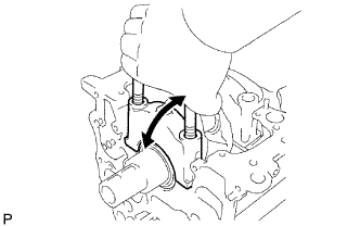
| 2. REMOVE NOZZLE HOLDER SEAL |
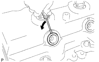 |
Using a small screwdriver, remove the holder seal by prying the portion between the holder seal and the cutout part of the cylinder head.
| 3. REMOVE CYLINDER HEAD COVER SUB-ASSEMBLY |
|
Using a small screwdriver, remove the holder seal by prying the portion between the holder seal and the cutout part of the cylinder head.
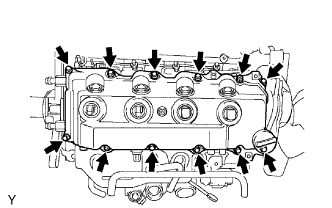 |
Remove the 10 bolts, 2 nuts, cylinder head cover and gasket.
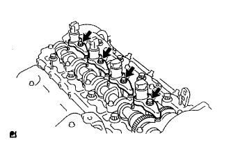
| 4. REMOVE INJECTOR ASSEMBLY |
 |
Remove the union bolt, 4 hollow screws, 5 gaskets and nozzle leakage pipe.
 |
Remove the 4 bolts, 4 washers, 4 nozzle holder clamps and 4 injectors.
Remove the O-ring and back-up ring from the injector.
Remove the 4 injection nozzle sheets from the cylinder head.
| 5. REMOVE CAMSHAFT TIMING PULLEY |
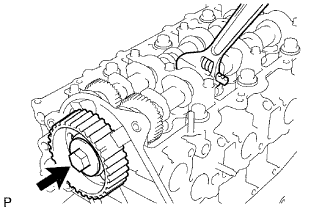 |
Remove the bolt of the camshaft timing pulley by holding the camshaft with a wrench.
Remove the camshaft timing pulley.
| 6. REMOVE NO. 2 TIMING BELT COVER |
Remove the 4 bolts, nuts and timing belt cover.
| 7. REMOVE CAMSHAFT |
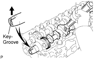 |
Face the key groove of the camshaft upward by turning the camshaft with a wrench.
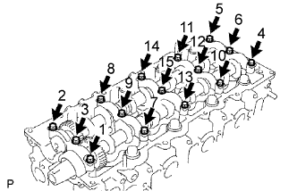 |
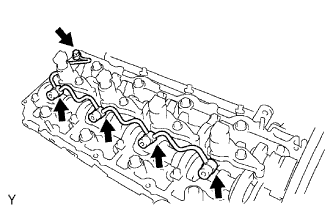
Uniformly loosen the 15 bearing cap bolts in several passes in the sequence shown in the illustration.
Remove the 5 bearing caps, oil seal and 2 camshafts.
| 8. REMOVE CYLINDER HEAD SUB-ASSEMBLY |
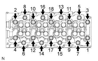 |
Uniformly loosen and remove the 18 cylinder head bolts in several passes in the sequence shown in the illustration.
Lift the cylinder head from the dowels on the cylinder block, and place the cylinder head on wooden blocks on a bench.
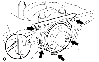
| 9. REMOVE WATER PUMP ASSEMBLY |
 |
Remove the 5 bolts, 2 nuts, water pump and gasket.
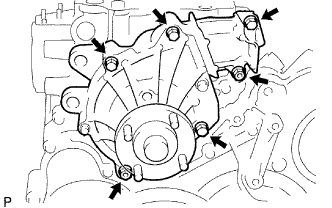
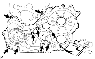
| 10. REMOVE TIMING GEAR CASE |
 |
Remove the 14 bolts and 2 nuts.
Pry the gear cover in the location shown in the illustration, and remove the gear cover together with the supply pump drive gear.
Remove the O-ring from the timing belt cover.
| 11. REMOVE SUPPLY PUMP GEAR |
 |
Using SST, remove the injection gear.
| 12. REMOVE NO. 1 CRANKSHAFT POSITION SENSOR |
Remove the bolt, sensor and O-ring.
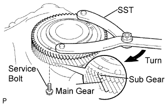
| 13. REMOVE NO. 1 IDLE GEAR |
 |
Secure the idle gears to the idle gear with the service bolt.
Remove the 2 bolts and thrust plate.
Turn the sub-gear and align the gear teeth of the idle main gear and sub-gear.
Remove the idle gear and sub-ear.
Remove the idle gear shaft.
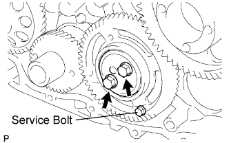
| 14. REMOVE NO. 2 IDLE SUB GEAR |
 |
Using SST, align the holes of the idler main gear and sub gears by turning the sub-ear clockwise, and install a service bolt.
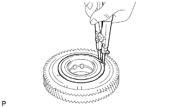 |
Using snap ring pliers, remove the snap ring.
Remove the wave washer, sub-ear and gear spring.
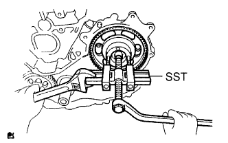
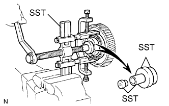
| 15. REMOVE CRANKSHAFT TIMING GEAR OR SPROCKET |
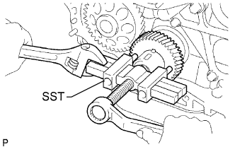 |
Using SST, remove the crankshaft timing gear.
| 16. REMOVE OIL PAN SUB-ASSEMBLY |
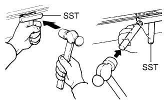 |
Remove the 4 bolts and oil level gauge sensor.
Remove the 22 bolts and 2 nuts.
Insert the blade of SST between the oil pan and cylinder block, cut through the applied sealer and remove the oil pan.
| 17. REMOVE OIL STRAINER SUB-ASSEMBLY |
Remove the 2 bolts, 2 nuts, oil strainer and gasket.
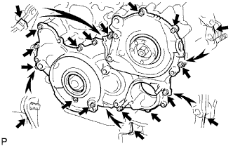
| 18. REMOVE TIMING GEAR CASE ASSEMBLY |
 |
Remove the union bolt and 8 bolts.
Pry the gear case in the location shown in the illustration, and remove the gear case, driven rotor and gasket.
Remove the 2 O-rings.
| 19. REMOVE ENGINE REAR OIL SEAL RETAINER |
 |
Remove the 5 bolts.
Using a screwdriver, remove the oil seal retainer by prying the portions between the oil seal retainer and cylinder block.
| 20. REMOVE SUPPLY PUMP GEAR BEARING |
 |
Using SST, remove the bearing.
| 21. REMOVE CYLINDER BLOCK OIL ORIFICE |
| 22. REMOVE PISTON AND CONNECTING ROD |
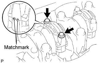 |
Check the matchmarks on the connecting rod and cap to ensure correct reassembly.
Remove the 2 connecting road cap bolts.
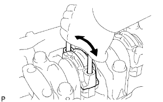 |
Using the 2 removed connecting rod bolts, pry the connecting rod cap back and forth, and remove the connecting cap.
Clean the crank pin and bearing.
Check the crank pin and bearing for pitting and scratches.
If the crank pin or bearing is damaged, replace the bearings. If necessary, grind or replace the crankshaft.
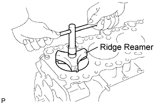 |
Using a ridge reamer, remove all the carbon from the top of the cylinder.
Push the piston, connecting rod assembly and upper bearing through the top of the cylinder block.
| 23. REMOVE PISTON PIN |
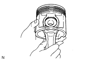 |
Check fit between the piston and piston pin.
Try to move the piston back and forth on the piston pin.
If any movement is felt, replace the piston and pin with a new piston and a set.
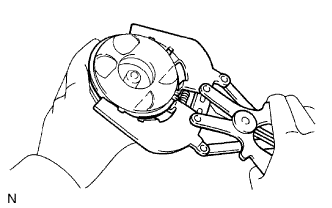 |
Using a piston ring expander, remove the 2 compression rings.
Remove the 2 side rails and oil ring by hand.
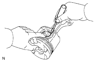 |
Disconnect the connecting rod from the piston.
Using a small screwdriver, pry off the 2 snaps ring from the piston.
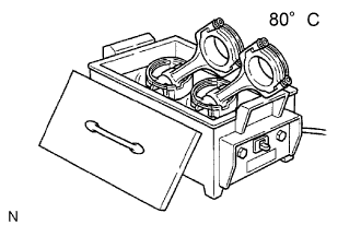 |
Gradually heat the piston to approximately. 80°C (176°F).
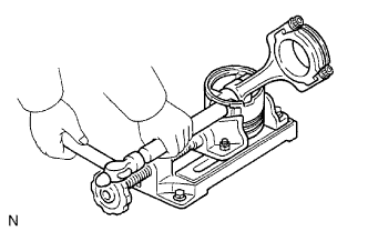 |
Using a plastic-faced hammer and brass bar, lightly tap out the piston pin and pin. Then remove the connecting rod.
| 24. REMOVE CRANKSHAFT SUB-ASSEMBLY |
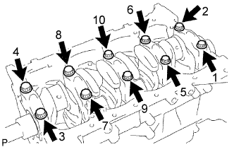 |
Uniformly loosen and remove the 10 crankshaft bearing cap bolts in several passes, in the sequence shown.
 |
Using the removed crankshaft bearing cap bolts, pry the cap back and forth, and remove the crankshaft bearing caps, lower crankshaft bearings and lower thrust washers (No. 3 crankshaft bearing cap only).
Lift out the crankshaft.
Remove the upper bearings and upper thrust washers from the cylinder block.
| 25. REMOVE NO. 1 OIL NOZZLE SUB-ASSEMBLY |
Remove the 4 check valves and oil nozzles.
| 26. REMOVE NO. 1 WITH HEAD STRAIGHT SCREW PLUG |
Remove the screw plug and gasket.
