ENGINE UNIT > INSPECTION |
| 1. INSPECT BACKLASH OF OIL PUMP GEAR TO CRANKSHAFT TIMING GEAR |
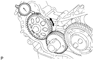 |
Using a dial indicator, measure the backlash.
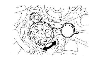
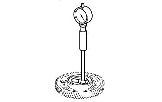
| 2. INSPECT NO. 1 IDLE GEAR THRUST CLEARANCE |
 |
Using a dial indicator, measure the thrust clearance.
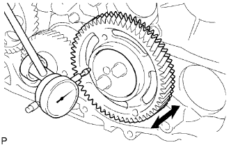
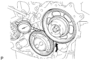
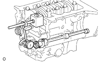
| 3. INSPECT BACKLASH OF CRANKSHAFT TIMING GEAR TO NO. 1 IDLE GEAR |
 |
Install the idle gear.
Using a dial indicator, measure the backlash.
Remove the idle gear.
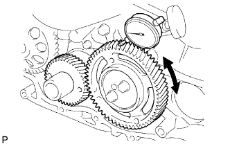
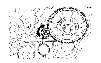
| 4. INSPECT BACKLASH OF OIL PUMP GEAR TO NO. 1 BALANCE SHAFT |
 |
Using a dial indicator, measure the backlash.
| 5. INSPECT BACKLASH OF SUPPLY PUMP GEAR TO NO. 2 BALANCE SHAFT |
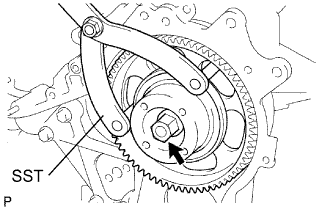 |
Install the supply pump with the 2 nuts.
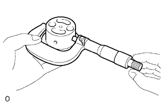
Using SST, install the supply pump gear with the nut.
 |
Using a dial indicator, measure the backlash.
| 6. INSPECT BACKLASH OF SUPPLY PUMP GEAR TO NO. 1 IDLE GEAR |
 |
Install the idle gear without sub gears.
Using a dial indicator, measure the backlash.
Using SST, remove the nut and supply pump gear.
Remove the 2 nuts and supply pump.
Remove the idle gear.
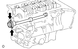
| 7. INSPECT NO. 1 IDLE GEAR OIL CLEARANCE |
 |
Using a cylinder gauge, measure the inside diameter of the idle gear.
 |
Using a micrometer, measure the diameter of the idle gear shaft.
Subtract the idle gear shaft diameter measurement from the idle gear inside diameter measurement.
| 8. INSPECT NO. 1 BALANCE SHAFT SUB-ASSEMBLY |
 |
Using a dial indicator, measure the thrust clearance by moving the balances shaft back and forth.
| 9. INSPECT NO. 2 BALANCE SHAFT SUB-ASSEMBLY |
 |
Using a dial indicator, measure the thrust clearance by moving the balance shaft back and forth.
| 10. INSPECT CYLINDER HEAD SET BOLT |
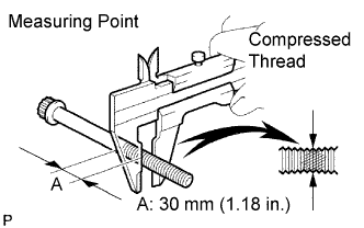 |
Using a vernier caliper, measure the minimum outside diameter of the compressed thread at the measuring point A.
| 11. INSPECT SUPPLY PUMP GEAR BEARING |
Check that bearing is not rough or worn.
If necessary, replace the bearing.
| 12. INSPECT CYLINDER BLOCK OIL ORIFICE |
Check the oil orifice for damage or clogging.
If necessary, replace the oil orifice.
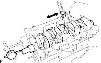
| 13. INSPECT CONNECTING ROD THRUST CLEARANCE |
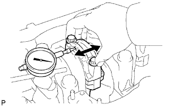 |
Using a dial indicator, measure the thrust clearance while moving the connecting rod back and forth.
| 14. INSPECT CONNECTING ROD OIL CLEARANCE |
Clean the crank pin and bearing.
Check the crank pin and bearing for pitting and scratches.
If the crank pin or bearing is damaged, replace the bearings. If necessary, grind or replace the crankshaft.
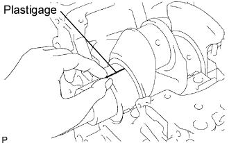
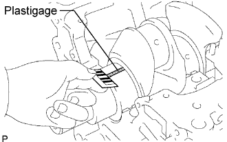
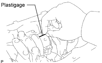 |
Lay a strip of Plastigage across the crank pin.
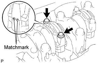 |
Install the connecting rod cap with the 2 bolts.
|
Check the matchmarks on the connecting rod and cap to ensure correct reassembly.
Remove the 2 bolts, connecting rod cap and lower bearing.
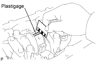  |
Measure the Plastigage at its widest point.
| STD | U/S 0.25, U/S 0.50 |
| 0.036 to 0.054 mm (0.0014 to 0.0021 in.) | 0.037 to 0.077 mm (0.0015 to 0.0030 in.) |
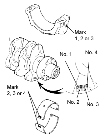
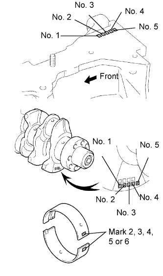
| Item | Number Mark | ||||||||
| Connecting rod cap | 1 | 2 | 3 | ||||||
| Crankshaft | 1 | 2 | 3 | 1 | 2 | 3 | 1 | 2 | 3 |
| Use bearing | 2 | 3 | 4 | 3 | 4 | 5 | 4 | 5 | 6 |
| Mark | Diameter |
| 1 | 62.014 to 62.020 mm (2.4415 to 2.4417 in.) |
| 2 | 62.020 to 62.026 mm (2.4417 to 2.4420 in.) |
| 3 | 62.026 to 62.032 mm (2.4420 to 2.4422 in.) |
| Mark | Diameter |
| 1 | 58.994 to 59.000 mm (2.3226 to 2.3228 in.) |
| 2 | 58.988 to 58.994 mm (2.3224 to 2.3226 in.) |
| 3 | 58.982 to 58.988 mm (2.3221 to 2.3224 in.) |
| Mark | Diameter |
| 1 | 1.486 to 1.489 mm (0.0585 to 0.0586 in.) |
| 2 | 1.489 to 1.492 mm (0.0586 to 0.0587 in.) |
| 3 | 1.492 to 1.495 mm (0.0587 to 0.0589 in.) |
| 4 | 1.495 to 1.498 mm (0.0589 to 0.0590 in.) |
| 5 | 1.498 to 1.501 mm (0.0590 to 0.0591 in.) |
Completely remove the Plastigage.
| 15. INSPECT CRANKSHAFT THRUST CLEARANCE |
 |
Using a dial indicator, measure the thrust clearance while prying the crankshaft back and forth with a screwdriver.
| STD | 2.430 to 2.480 mm (0.0957 to 0.0976 in.) |
| O/S 0.125 | 2.493 to 2.543 mm (0.0981 to 0.1001 in.) |
| O/S 0.250 | 2.680 to 2.730 mm (0.1055 to 0.1074 in.) |
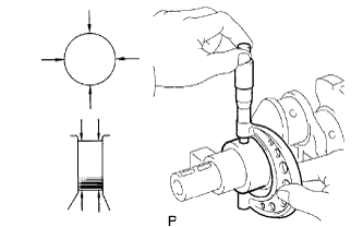
| 16. INSPECT CRANKSHAFT OIL CLEARANCE |
Clean each main journal and bearing.
Check each crankshaft journal and bearing for pitting and scratches.
If the journal or bearing is damaged, replace the bearings. If necessary, grind or replace the crankshaft.
Place the crankshaft on the cylinder block.
 |
Lay a strip of Plastigage across each journal.
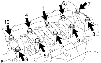 |
Install the 5 crankshaft bearing caps with the 10 bolts.
Remove the 10 bolts and 5 crankshaft bearing caps.
  |
Measure the Plastigage at its widest point.
| STD | 0.030 to 0.048 mm (0.0012 to 0.0019 in.) |
| O/S 0.25, O/S 0.50 | 0.037 to 0.077 mm (0.0015 to 0.0030 in.) |
| Item | Number Mark | ||||||||
| Cylinder block | 1 | 2 | 3 | ||||||
| Crankshaft | 1 | 2 | 3 | 1 | 2 | 3 | 1 | 2 | 3 |
| Use bearing | 2 | 3 | 4 | 3 | 4 | 5 | 4 | 5 | 6 |
| Mark | Diameter |
| 1 | 75.000 to 75.006 mm (2.9528 to 2.9530 in.) |
| 2 | 75.006 to 75.012 mm (2.9530 to 2.9532 in.) |
| 3 | 75.012 to 75. 018 mm (2.9532 to 2.9535 in.) |
| Mark | Diameter |
| 1 | 69.994 to 70.000 mm (2.7557 to 2.7559 in.) |
| 2 | 69.988 to 69.994 mm (2.7554 to 2.7557 in.) |
| 3 | 69.982 to 69.988 mm (2.7552 to 2.7554 in.) |
| Mark | Diameter |
| 2 | 2.482 to 2.485 mm (0.0977 to 0.0978 in.) |
| 3 | 2.485 to 2.488 mm (0.0978 to 0.0980 in.) |
| 4 | 2.488 to 2.491 mm (0.0980 to 0.0981 in.) |
| 5 | 2.491 to 2.494 mm (0.0981 to 0.0982 in.) |
| 6 | 2.494 to 2.497 mm (0.0982 to 0.0983 in.) |
Completely remove the Plastigage.
| 17. INSPECT OIL CHECK VALVE SUB-ASSEMBLY |
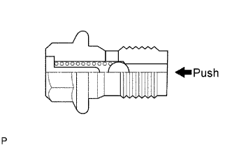 |
Push the valve with a wooden stick to check if it is stuck.
If stuck, replace the check valve.
| 18. INSPECT NO. 1 OIL NOZZLE SUB-ASSEMBLY |
Check the oil nozzles for damage or clogging.
If necessary, replace the oil nozzle.
| 19. CLEAN CYLINDER BLOCK SUB-ASSEMBLY |
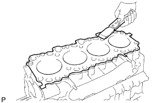 |
Using a gasket scraper, remove all the gasket material from the top surface of the cylinder block.
Using a soft brush and solvent, thoroughly clean the cylinder block.
| 20. INSPECT CYLINDER BLOCK SUB-ASSEMBLY |
 |
Inspect for flatness.
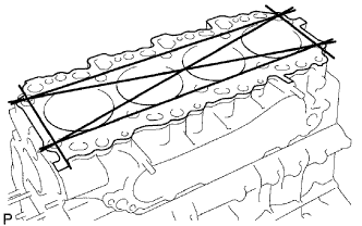
Using a precision straightedge and feeler gauge, measure the surface contacting the cylinder head cap for warpage.
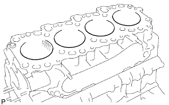 |
Visually check the cylinder for vertical scratches.
If deep scratches are present, rebore all the 4 cylinders. If necessary, replace the cylinder block.
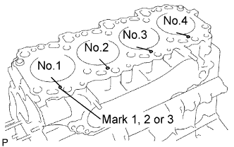 |
Inspect the cylinder bore diameter.
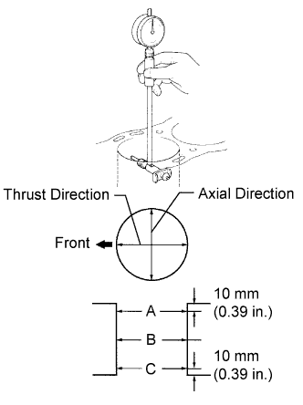 |
Using a cylinder gauge, measure the cylinder bore diameter at positions A, B and C in the thrust and axial directions.
| Mark 1 | Mark 2 | Mark 3 |
| 96.000 to 96.010 mm (3.7795 to 3.7799 in.) | 96.010 to 96.020 mm (3.7799 to 3.7803 in.) | 96.020 to 96.030 mm (3.7803 to 3.7807 in.) |
| STD | O/S 0.50 | O/S 0.75 | O/S 1.00 |
| 96.23 mm (3.7886 in.) | 96.73 mm (3.8082 in.) | 96.98 mm (3.8181 in.) | 97.23 mm (3.8279 in.) |
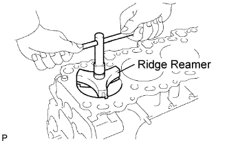 |
Remove the cylinder ridge.
If the wear is less than 0.2 mm (0.008 in.), using a ridge reamer, grind the top of the cylinder.
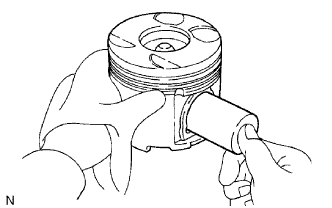
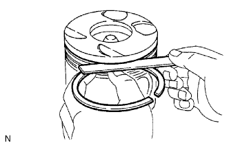
| 21. CLEAN PISTON |
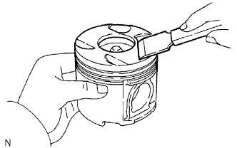 |
Using a gasket scraper, remove the carbon from the piston top.
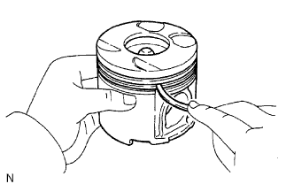 |
Using a groove cleaning tool or broken ring, clean the piston ring grooves.
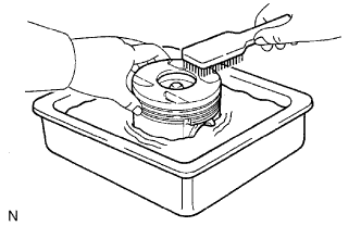 |
Using solvent and a brush, thoroughly clean the piston.
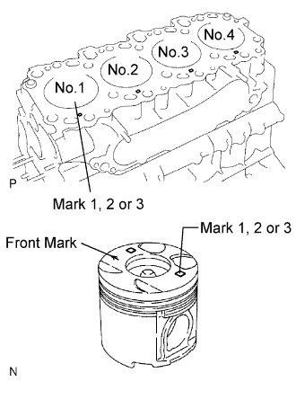
| 22. INSPECT WITH PISTON SUB-ASSEMBLY |
 |
Inspect the piston oil clearance.
Using a micrometer, measure the piston diameter at right angles to the piston center line, the indicated distance from the piston head.
| Piston | Mark | Diameter |
| STD | Mark 1 | 95.92 to 95.93 mm (3.77637 to 3.77676 in.) |
| STD | Mark 2 | 95.93 to 95.94 mm (3.77676 to 3.77715 in.) |
| STD | Mark 3 | 95.94 to 95.95 mm (3.77716 to 3.77755 in.) |
| O/S 0.50 | - | 96.42 to 96.70 mm (3.7960 to 3.8070 in.) |
| O/S 0.75 | - | 96.67 to 96.95 mm (3.8058 to 3.8169 in.) |
| O/S 1.00 | - | 96.92 to 97.20 mm (3.8157 to 3.8267 in.) |
Measure the cylinder bore diameter in the thrust directions.
 |
Subtract the piston diameter measurement from the cylinder bore diameter measurement.
 |
Using a micrometer, measure the piston pin diameter.
 |
Inspect the piston pin fit.
At 80°C (176°F), check that the piston pin can be pushed into the piston pin hole with your thumb.
If the pin can be installed at a lower temperature, replace the piston and pin as a set.
| 23. INSPECT PISTON RING SET |
 |
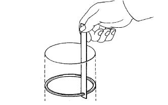
Inspect the piston ring groove clearance.
Using a feeler gauge, measure the clearance between a new piston ring and the wall of the ring groove.
| No. 1 | No. 2 | Oil |
| 0.091 to 0.135 mm (0.0036 to 0.0053 in.) | 0.090 to 0.130 mm (0.0036 to 0.0051 in.) | 0.030 to 0.075 mm (0.0012 to 0.0027 in.) |
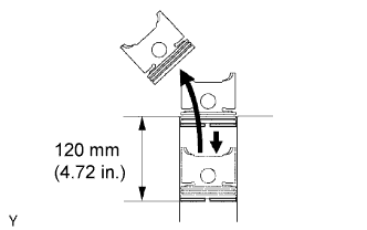 |
Inspect the piston ring end gap.
Insert the piston ring into the cylinder bore.
Using a piston, push the piston ring a little beyond the bottom of the ring travel and 120 mm (4.72 in.) from the top of the cylinder block.
 |
Using a feeler gauge, measure the end gap.
| No. 1 | No. 2 | Oil |
| 0.27 to 0.39 mm (0.0106 to 0.0154 in.) | 0.47 to 0.57 mm (0.0185 to 0.0224 in.) | 0.20 to 0.40 mm (0.0079 to 0.0157 in.) |
| No. 1 | No. 2 | Oil |
| 0.85 mm (0.0335 in.) | 1.07 mm (0.0421 in.) | 0.77 mm (0.0303 in.) |
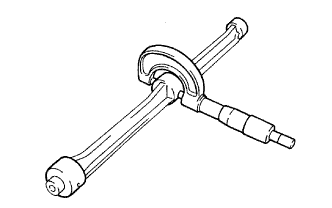
| 24. INSPECT CONNECTING ROD SUB-ASSEMBLY |
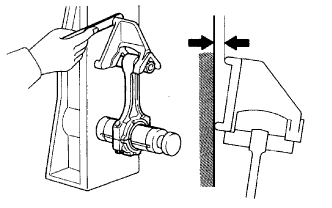 |
Using a rod aligner and feeler gauge, check the connecting rod alignment.
Check if it is bend.
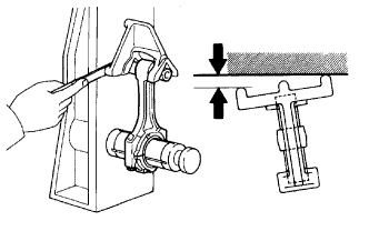 |
Check if the rod is twisted.
| 25. INSPECT PISTON PIN OIL CLEARANCE |
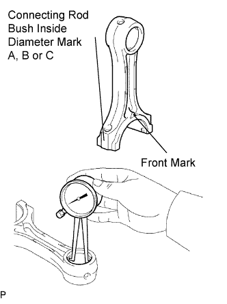 |
Inspect the piston pin oil clearance.
Using a caliper gauge, measure the inside diameter of the connecting rod bush.
| Size Mark | Diameter |
| A | 34.012 to 34.016 mm (1.3390 to 1.3392 in.) |
| B | 34.016 to 34.020 mm (1.3392 to 1.3393 in.) |
| C | 34.020 to 34.024 mm (1.3392 to 1.3395 in.) |
Subtract the piston pin diameter measurement from the bush inside diameter measurement.
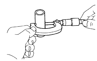
| 26. INSPECT CONNECTING ROD BOLT |
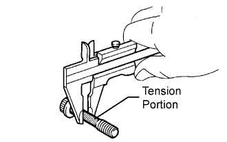 |
Using a vernier caliper, measure the tension portion of the connecting rod bolt.
| 27. INSPECT NO. 1 BALANCE SHAFT SUB-ASSEMBLY |
 |
Using a cylinder gauge, measure the inside diameter of the balance shaft bearing.
| No. 1 | No. 2 | No. 3 |
| 42.000 to 42.020 mm (1.6535 to 1.6543 in.) | 41.000 to 41.020 mm (1.6142 to 1.6150 in.) | 32.000 to 32.020 mm (1.2598 to 1.2606 in.) |
 |
Using a micrometer, measure the outside diameter of the balance shaft main journals.
| No. 1 | No. 2 | No. 3 |
| 41.941 to 41.960 mm (1.6512 to 1.6520 in.) | 40.931 to 40.950 mm (1.6115 to 1.6122 in.) | 31.941 to 31.960 mm (1.2575 to 12583 in.) |
Subtract the outside diameter of the balance shaft main journal from the inside diameter to the balance shaft bearing.
| No. 1 | No. 2 | No. 3 |
| 0.040 to 0.079 mm (0.0016 to 0.0031 in.) | 0.040 to 0.079 mm (0.0016 to 0.0031 in.) | 0.050 to 0.089 mm (0.0020 to 0.0035 in.) |
| No. 1 | No. 2 | No. 3 |
| 0.18 mm (0.0071 in.) | 0.19 mm (0.0075 in.) | 0.18 mm (0.0071 in.) |
| 28. INSPECT NO. 2 BALANCE SHAFT SUB-ASSEMBLY |
 |
Using a cylinder gauge, measure the inside diameter of the balance shaft bearing.
| No. 1 | No. 2 | No. 3 |
| 42.000 to 42.020 mm (1.6535 to 1.6543 in.) | 41.000 to 41.020 mm (1.6142 to 1.6150 in.) | 32.000 to 32.020 mm (1.2598 to 1.2606 in.) |
|
Using a micrometer, measure the outside diameter of the balance shaft main journals.
| No. 1 | No. 2 | No. 3 |
| 41.941 to 41.960 mm (1.6512 to 1.6520 in.) | 40.931 to 40.950 mm (1.6115 to 1.6122 in.) | 31.941 to 31.960 mm (1.2575 to 12583 in.) |
Subtract the outside diameter of the balance shaft main journal from the inside diameter to the balance shaft bearing.
| No. 1 | No. 2 | No. 3 |
| 0.040 to 0.079 mm (0.0016 to 0.0031 in.) | 0.040 to 0.079 mm (0.0016 to 0.0031 in.) | 0.050 to 0.089 mm (0.0020 to 0.0035 in.) |
| No. 1 | No. 2 | No. 3 |
| 0.18 mm (0.0071 in.) | 0.19 mm (0.0075 in.) | 0.18 mm (0.0071 in.) |
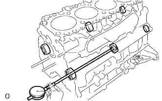
| 29. INSPECT CRANKSHAFT |
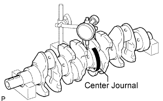 |
Inspect for circle runout.
Place the crankshaft on V-blocks.
Using a dial indicator, measure the circle runout at the center journal.
 |
Inspect the main journals and crank pins.
Using a micrometer, measure the diameter of each main journal and crank pin.
| Mark 1 | Mark 2 | Mark 3 |
| 69.994 to 70.000 mm (2.75566 to 2.75590 in.) | 69.988 to 69.994 mm (2.75543 to 2.75566 in.) | 69.982 to 69.988 mm (2.75519 to 2.75543 in.) |
| Mark 1 | Mark 2 | Mark 3 |
| 58.994 to 59.000 mm (2.32259to 2.32283 in.) | 58.988 to 59.994 mm (2.32236 to 2.32259 in.) | 58.982 to 58.988 mm (2.32212 to 2.32239 in.) |
Check each main journal and crank pin for taper and out-of-round as shown.
If necessary, grind and hone the main journals and/or crank pins.
Grind and hone the main journals and/or crank pins to the finished undersized diameter.
Install new main journal and/or crankshaft pin undersized bearing.
| 30. INSPECT CRANKSHAFT BEARING CAP BOLT |
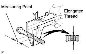 |
Using a vernier caliper, measure the minimum diameter of the compressed thread at the measuring point.
