ENGINE ASSEMBLY > REMOVAL |
| 1. DISCONNECT CABLE FROM NEGATIVE BATTERY TERMINAL |
| 2. REMOVE HOOD SUB-ASSEMBLY |
Disconnect the washer nozzle hose.
Remove the 4 bolts and hood.
| 3. REMOVE NO. 1 ENGINE UNDER COVER (for 4WD) |
Remove the 4 bolts and under cover.
| 4. REMOVE NO. 2 ENGINE UNDER COVER (for 4WD) |
Remove the 2 bolts and under cover.
| 5. DRAIN ENGINE OIL |
Remove the oil filler cap.
Remove the oil drain plug, and drain the engine oil from the oil pan.
| 6. LOOSEN FUEL TANK CAP ASSEMBLY |
| 7. DRAIN FUEL |
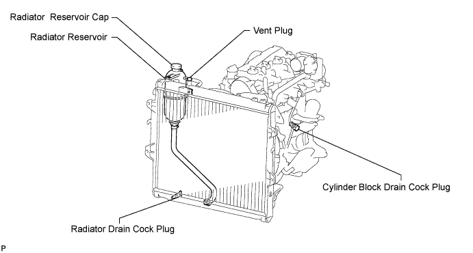
| 8. DRAIN ENGINE COOLANT |
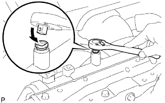 |
Drain the coolant by removing the reservoir cap and, using a wrench, remove the vent plug.
Loosen the cylinder block drain cock plug and the radiator drain cock plug.
| 9. DRAIN TRANSMISSION OIL |
R151/R151F:
Drain transmission oil (Click here).
G50/G55:
Drain transmission oil (Click here).
| 10. REMOVE BATTERY BRACKET |
| 11. REMOVE BATTERY AND BATTERY TRAY |
| 12. REMOVE AIR CLEANER ASSEMBLY |
Disconnect the IAT sensor connector.
Loosen the hose clamp.
Remove the 3 bolts and air cleaner.
| 13. REMOVE RADIATOR ASSEMBLY |
Remove the radiator assembly (Click here).
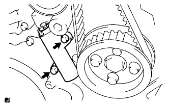
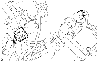
| 14. REMOVE STARTER ASSEMBLY |
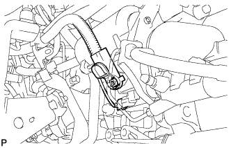 |
Disconnect the starter connector.
Remove the nut and disconnect the starter wire.
Remove the clutch release cylinder.
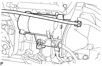 |
Remove the nut, bolt, ground cable and starter.
| 15. REMOVE FRONT EXHAUST PIPE ASSEMBLY |
Remove the 2 bolts and 2 compression springs.
Disconnect the front pipe from the outlet pipe and remove the gasket.
Remove the front pipe from the pipe support.
| 16. REMOVE PROPELLER SHAFT ASSEMBLY |
Front Side:
Remove the propeller shaft assembly (Click here).
Rear Side:
Remove the propeller shaft assembly (Click here).
| 17. REMOVE TRANSMISSION ASSEMBLY |
R151/R151F:
Remove the transmission assembly (Click here).
G50/G55:
Remove the transmission assembly (Click here).
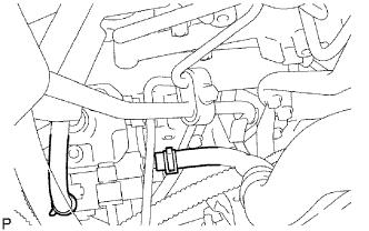
| 18. DISCONNECT HOSES AND CONNECTORS |
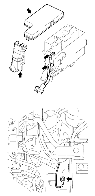 |
Remove the engine room relay block cover (upper).
Remove the No. 1 engine room relay block cover (side).
Remove the nut and disconnect the engine room J/B wire.
Disconnect the 2 engine room junction block connectors.
Remove the bolt and disconnect the ground cable.
 |
Disconnect the 2 injector driver connectors.
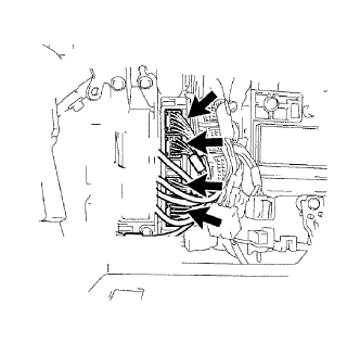 |
Disconnect the 4 ECM connectors.
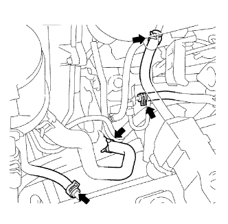 |
Disconnect the 2 fuel hoses.
Disconnect the vacuum pump hose.
Disconnect the oil reservoir to pump hose.
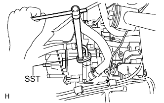 |
Using SST, disconnect the pressure feed tube.
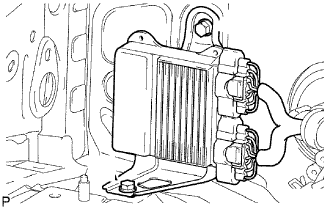
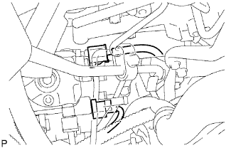
| 19. DISCONNECT COOLER COMPRESSOR ASSEMBLY |
Remove the 4 bolts and disconnect the cooler compressor.
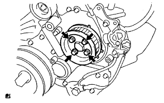
| 20. REMOVE CLUTCH COVER ASSEMBLY |
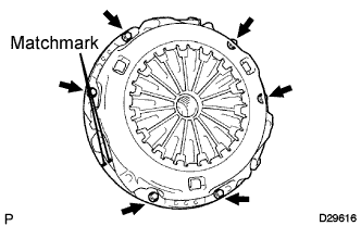 |
Place matchmarks on the clutch cover and flywheel.
Loosen each set bolt one turn at a time until spring tension is released.
Remove the 6 set bolts and pull off the clutch cover.
| 21. REMOVE CLUTCH DISC ASSEMBLY |
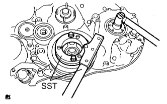
| 22. REMOVE FLYWHEEL SUB-ASSEMBLY |
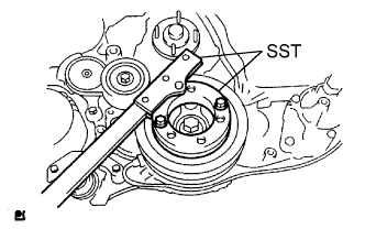 |
Using SST, hold the crankshaft.
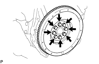 |
Remove the 8 bolts and flywheel.
| 23. REMOVE REAR END PLATE |
Remove the bolt and end plate.
| 24. REMOVE ENGINE ASSEMBLY |
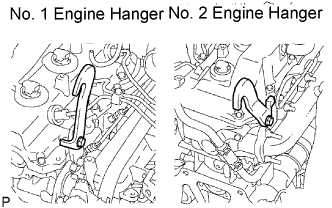 |
Set the No. 1 engine hanger and No. 2 engine hanger to the locations shown in the illustration.
| Parts Name | Parts No. |
| Engine hanger No. 1 | 12284-30020 |
| Bolt (91512-61014) | |
| Engine hanger No. 2 | 12282-67020 |
| Bolt (91642-81030) |
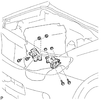 |
Hold the engine with the engine sling device and chain block.
Remove the 4 bolts and 4 nuts.
Remove the engine by operating the engine sling device and chain block.
| 25. FIX ENGINE ON ENGINE STAND |
| 26. REMOVE ENGINE WIRE |
Disconnect the engine wire from the engine.
| 27. REMOVE NO. 1 TIMING BELT COVER |
 |
Remove the bolt and water hose clamp.
Remove the wire harness clamp.
Remove the 6 bolts and timing belt cover.
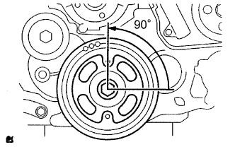
| 28. REMOVE TIMING BELT |
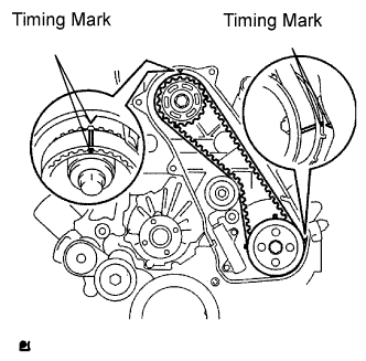 |
Turn the crankshaft clockwise and align the timing marks as shown in the illustration.
 |
Uniformly loosen the 2 bolts and remove the timing belt tensioner.
Remove the timing belt.
Using a 10 mm hexagon wrench, remove the bolt, timing belt idler and washer.
| 29. REMOVE NO. 1 TIMING BELT IDLER SUB-ASSEMBLY |
| 30. REMOVE NO. 1 TIMING BELT TENSIONER ASSEMBLY |
| 31. REMOVE CRANKSHAFT PULLEY |
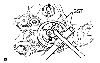 |
Using SST, remove the pulley bolt.
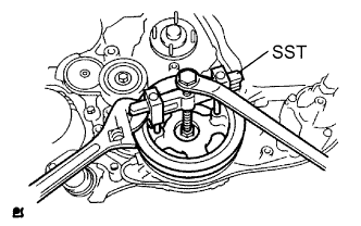 |
Using SST, remove the pulley.
| 32. REMOVE CAMSHAFT TIMING PULLEY |
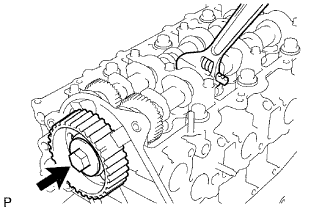 |
Remove the bolt of the camshaft timing pulley by holding the camshaft with a wrench.
Remove the camshaft timing pulley.
| 33. REMOVE VENTILATION HOSE HEAT INSULATOR |
Remove the 2 bolts and insulator.
| 34. DISCONNECT VENTILATION HOSE |
| 35. REMOVE VENTILATION PIPE |
| 36. REMOVE TURBO OIL INLET PIPE SUB-ASSEMBLY |
| 37. REMOVE EXHAUST MANIFOLD |
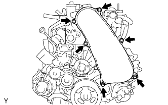
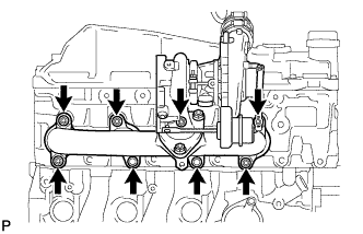 |
Remove the 8 nuts and exhaust manifold with turbocharger as shown in the illustration.
| 38. INSPECT EXHAUST MANIFOLD |
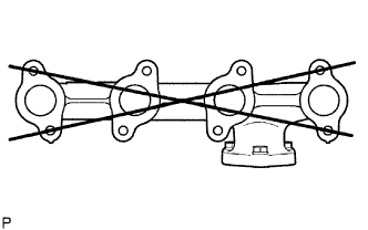 |
Using a precision straightedge and feeler gauge, measure the surface contacting the cylinder head for warpage.
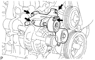
| 39. REMOVE GENERATOR BRACKET |
| 40. REMOVE GENERATOR ASSEMBLY |
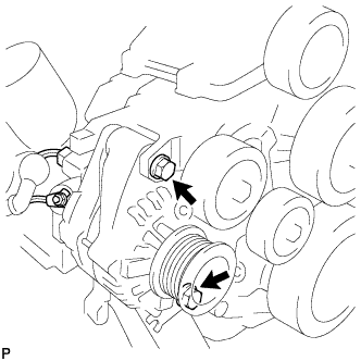 |
Remove the nut and generator wire.
Disconnect the generator connector.
Remove the 2 bolts, adjusting bar and generator.
| 41. REMOVE V-RIBBED BELT TENSIONER ASSEMBLY |
 |
Remove the 4 bolts and belt tensioner.
| 42. REMOVE NO. 1 COMPRESSOR MOUNTING BRACKET |
Remove the 4 bolts and mounting bracket.
| 43. REMOVE THERMOSTAT |
| 44. REMOVE WATER OUTLET |
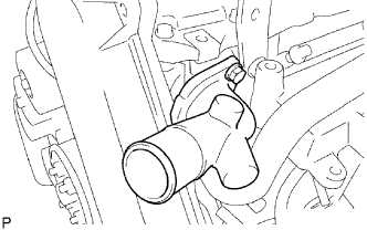 |
Remove the 2 bolts and water outlet.
| 45. REMOVE GLOW PLUG ASSEMBLY |
 |
Using a 12 mm deep socket wrench, remove the 4 glow plugs.
| 46. REMOVE MANIFOLD STAY |
 |
Remove the 2 bolts and stay.
| 47. REMOVE DIESEL THROTTLE BODY ASSEMBLY |
 |
Disconnect the 2 connectors.
 |
Remove the 2 bolts, 2 nuts, throttle body and gasket.
| 48. REMOVE DIESEL THROTTLE BODY BRACKET |
 |
Remove the 3 bolts and bracket.
Remove the 2 nuts, bolt from the air connector.
| 49. REMOVE INTAKE AIR CONNECTOR |
 |
Remove the 2 bolts, air connector and bracket.
| 50. REMOVE OIL FILTER SUB-ASSEMBLY |
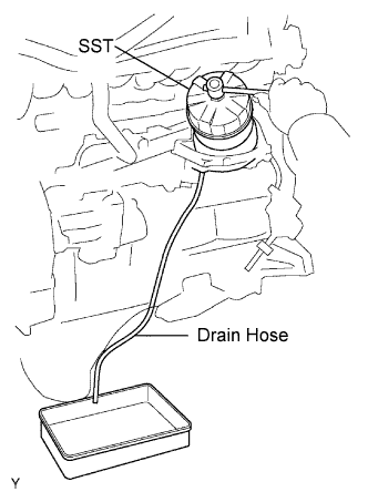 |
Using SST, remove the oil filter.
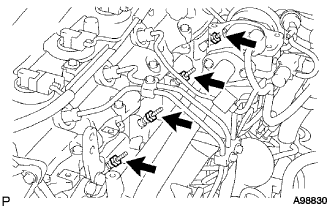
| 51. REMOVE INJECTION PIPE |
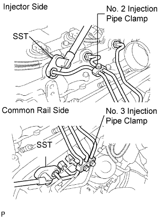 |
Remove the 2 nuts and No. 3 injection pipe clamp.
Remove the bolt and No. 2 injection pipe clamp.
Using SST, loosen the union nuts and remove the No. 1, No. 2 and No. 3 injection pipes.
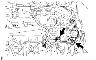 |
Remove the 2 bolts and disconnect the 2 injection pipe clamps.
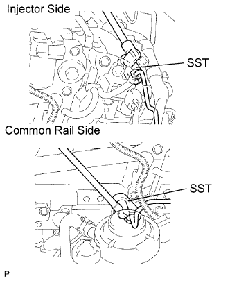 |
Using SST, loosen the union nuts and remove the No. 4 injection pipe.
| 52. REMOVE NO. 2 NOZZLE LEAKAGE PIPE ASSEMBLY |
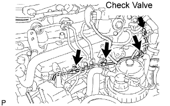 |
Disconnect the 2 fuel hoses.
Remove the check valve, 3 bolts, leakage pipe and gasket.
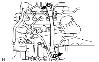
| 53. REMOVE FUEL INLET PIPE SUB-ASSEMBLY |
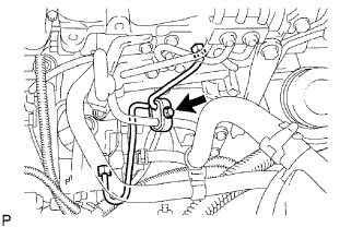 |
Remove the bolt and clamp.
Remove the 2 bolts and oil level gauge guide.
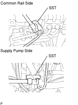 |
Using SST, loosen the union nuts and remove the fuel inlet pipe.
| 54. REMOVE COMMON RAIL ASSEMBLY |
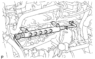 |
Disconnect the fuel pressure sensor connector.
Remove the 2 bolts and common rail.
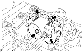
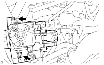
| 55. REMOVE FUEL SUPPLY PUMP ASSEMBLY |
|
Remove the bolt and clamp.
Remove the 2 bolts and oil level gauge guide.
|
Using SST, loosen the union nuts and remove the fuel inlet pipe.
 |
Disconnect the 2 fuel hoses.
 |
Disconnect the 2 connectors.
 |
Remove the 4 bolts indicated by the arrows in the illustration.
Remove the No. 2 camshaft timing pulley flange and pump drive shaft pulley.
 |
Remove the set nut and O-ring while holding the crankshaft pulley by using SST.
 |
Loosen the 2 nuts.
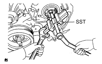 |
Using SST, disconnect the pump from the injection gear.
Remove the 2 nuts and pump.
Remove the O-ring.
| 56. REMOVE OIL LEVEL GAUGE GUIDE |
Remove the bolt, oil level gauge guide and O-ring.
| 57. REMOVE INTAKE MANIFOLD |
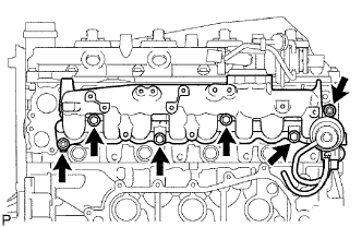 |
Remove the 4 bolts, 2 nuts, manifold and gasket.
| 58. INSPECT INTAKE MANIFOLD |
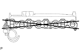 |
Using a precision straightedge and feeler gauge, measure the surface contacting the cylinder head for warpage.
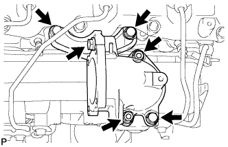
| 59. REMOVE OIL COOLER COVER SUB-ASSEMBLY |
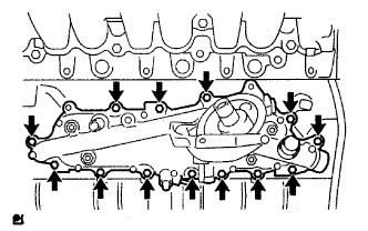 |
Disconnect the oil pressure switch connector and wire harness.
Remove the 13 bolts, 2 nuts and oil cooler cover.
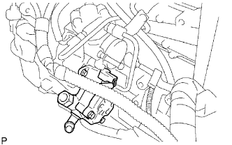
| 60. REMOVE VACUUM PUMP ASSEMBLY |
 |
Remove the 2 nuts, vacuum pump and 2 O-rings.
| 61. REMOVE VANE PUMP ASSEMBLY |
 |
Remove the 2 nuts, vane pump and O-ring.
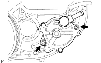
| 62. REMOVE CRANKSHAFT POSITION SENSOR |
Remove the bolt, sensor and O-ring.
| 63. REMOVE CAMSHAFT POSITION SENSOR |
Remove the bolt, sensor and O-ring.
| 64. REMOVE ENGINE COOLANT TEMPERATURE SENSOR |
Using a 17 mm deep socket wrench, remove the sensor.
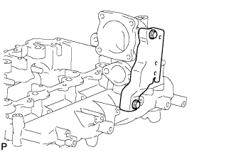
| 65. REMOVE NO. 1 FRONT ENGINE MOUNTING BRACKET RH |
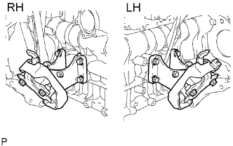 |
Remove the 4 bolts and mounting bracket.
| 66. REMOVE NO. 1 FRONT ENGINE MOUNTING BRACKET LH |
Remove the 4 bolts and mounting bracket.
