ENGINE ASSEMBLY > INSTALLATION |
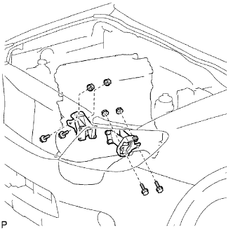
| 1. INSTALL NO. 1 FRONT ENGINE MOUNTING BRACKET RH |
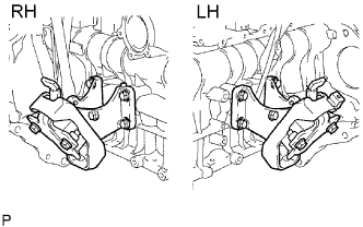 |
Install the mounting bracket with the 4 bolts.
| 2. INSTALL NO. 1 FRONT ENGINE MOUNTING BRACKET LH |
Install the mounting bracket with the 4 bolts.
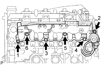
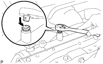
| 3. INSTALL ENGINE COOLANT TEMPERATURE SENSOR |
Using a 17 mm deep socket wrench, install the sensor.
| 4. INSTALL CAMSHAFT POSITION SENSOR |
Apply clean engine oil to a new O-ring.
Install the O-ring to the sensor.
Install the sensor with the bolt.
| 5. INSTALL CRANKSHAFT POSITION SENSOR |
Apply clean engine oil to a new O-ring.
Install the O-ring to the sensor.
Install the sensor with the bolt.
| 6. INSTALL VANE PUMP ASSEMBLY |
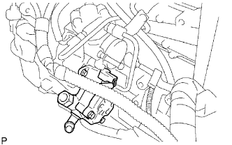 |
Install a new O-ring to the vane pump.
Install the vane pump with the 2 nuts.
| 7. INSTALL VACUUM PUMP ASSEMBLY |
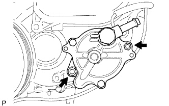 |
Install a new O-ring to the vacuum pump.
Install the vacuum pump with the 2 nuts.
| 8. INSTALL OIL COOLER COVER SUB-ASSEMBLY |
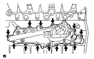 |
Install a new gasket and the oil cooler cover with the 13 bolts and 2 nuts.
Connect the oil pressure connector and install the wire harness.
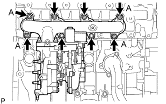
| 9. INSTALL INTAKE MANIFOLD |
 |
Install a new gasket and the manifold to the cylinder head with the 4 bolts and 2 nuts in the order shown in the illustration.
| 10. INSTALL OIL LEVEL GAUGE GUIDE |
Apply clean engine oil to a new O-ring.
Install the O-ring to the level gauge.
Install the level gauge with the bolt.
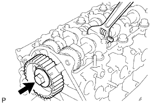
| 11. INSTALL FUEL SUPPLY PUMP ASSEMBLY |
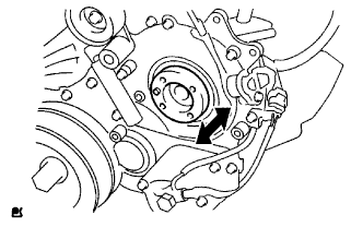 |
Check that the supply pump gear in the timing gear case moves back and forth smoothly.
Install a new O-ring to the pump.
Apply a light coat of engine oil to the O-ring.
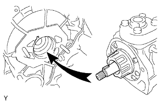 |
Align the set key on the drive shaft with the groove of the injection gear.
 |
Install the pump with the 2 nuts.
Set a new O-ring before tightening the set nut.
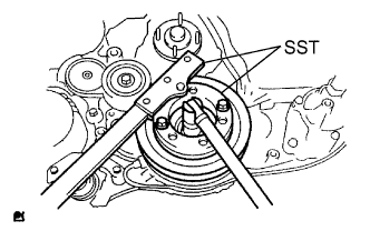
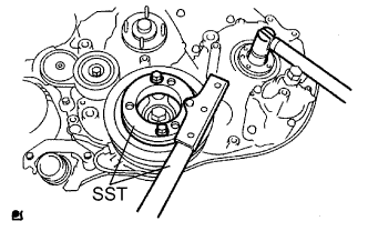 |
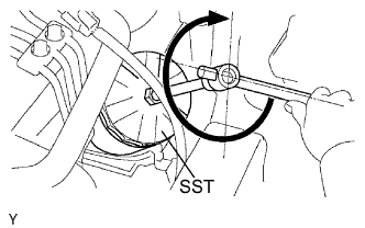
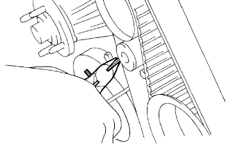
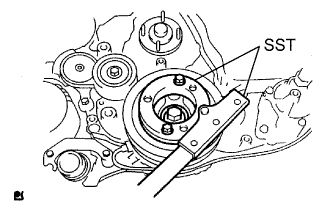
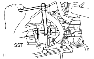
Using SST, hold the crankshaft pulley and install the set nut.
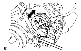 |
Move the pump drive shaft pulley back and forth to check the thrust clearance of the injection pump drive shaft.
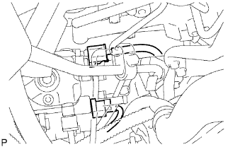 |
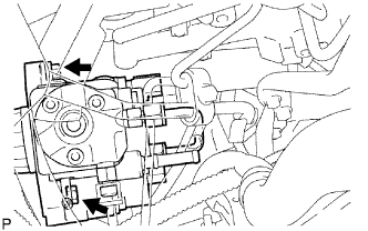
Connect the 2 connectors.
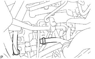 |
Connect the 2 fuel hoses.
 |
Temporarily install the fuel inlet pipe with the union nuts.
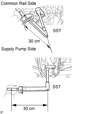
Using SST, tighten the injection pipe union nut on the common rail side.
Using SST, tighten the injection pipe union nut on the supply pump side.
Install the oil level gauge guide with the 2 bolts.
 |
Install the clamp with the bolt.
| 12. INSTALL COMMON RAIL ASSEMBLY |
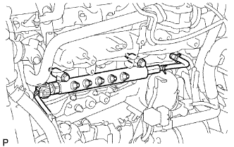 |
Install the common rail with the 2 bolts.
Connect the fuel pressure sensor connector.
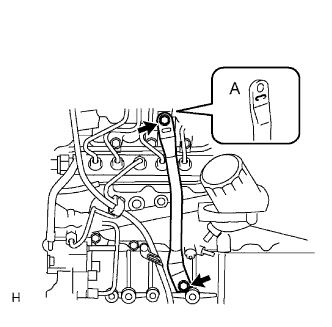
| 13. INSTALL FUEL INLET PIPE SUB-ASSEMBLY |
|
Temporarily install the fuel inlet pipe with the union nuts.
Using SST, tighten the inlet pipe union nut on the common rail side.
Using SST, tighten the inlet pipe union nut on the supply pump side.
Install the oil level gauge guide with the 2 bolts.
|
Install the clamp with the bolt.
| 14. INSTALL NO. 2 NOZZLE LEAKAGE PIPE ASSEMBLY |
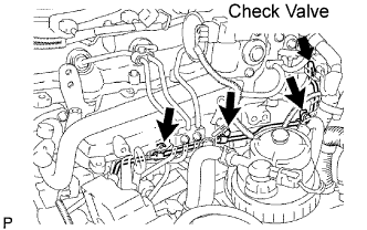 |
Temporarily install the leakage pipe with the 3 bolts.
Temporarily install a new gasket with the check valve.
Fully tighten the 3 bolts and check valve.
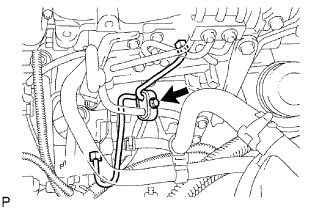
Connect the 2 fuel hoses.
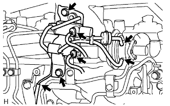
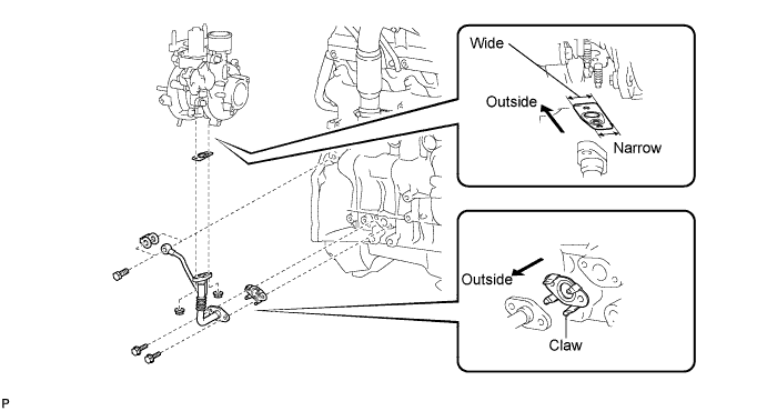
| 15. INSTALL INJECTION PIPE |
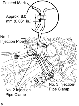 |
Temporarily install the No. 1, No. 2 and No. 3 injection pipes with the union nuts.
Install the No. 2 and No. 3 injection pipe clamps with the bolt and 2 nuts, as shown in the illustration.
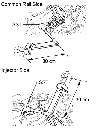 |
Using SST, tighten the injection pipe union nuts on the common rail side.
Using SST, tighten the injection pipe union nuts on the injector side.
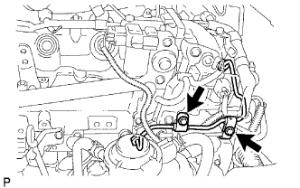 |
Temporarily install the No. 4 injection pipe with the union nuts.
Install 2 new injection pipe clamps with the 2 bolts.
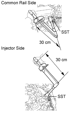 |
Using SST, tighten the injection pipe union nuts on the common rail side.
Using SST, tighten the injection pipe union nuts on the injector side.
| 16. INSTALL OIL FILTER SUB-ASSEMBLY |
Check and clean the oil filter installation surface.
Apply clean engine oil to the gasket of a new oil filter.
Lightly screw the oil filter into place by hand. Tighten it until the gasket contacts the seat.
 |
Using SST, tighten the oil filter. Depending on the work space available, choose from the following.
If enough space is available, use a torque wrench to tighten the oil filter.
If enough space is not available to use a torque wrench, tighten the oil filter 3/4 turn by hand or with a common wrench.
| 17. INSTALL EGR VALVE ASSEMBLY |
Install a new gasket and the EGR valve.
| 18. INSTALL NO. 1 EGR PIPE SUB-ASSEMBLY |
 |
Install 2 new gaskets and the pipe with the 2 nuts and 2 bolts.
| 19. INSTALL INTAKE AIR CONNECTOR |
 |
Install a new gasket and the air connector with the 2 nuts and bolt.
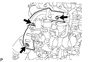
| 20. INSTALL DIESEL THROTTLE BODY BRACKET |
 |
Install the bracket with the 3 bolts.
| 21. INSTALL DIESEL THROTTLE BODY ASSEMBLY |
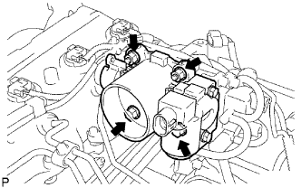 |
Install a new gasket and the throttle body with the 2 bolts and 2 nuts.
 |
Connect the 2 connectors.
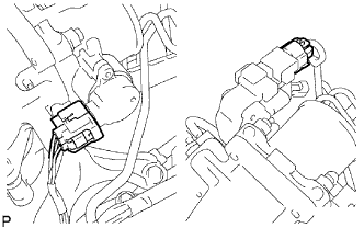
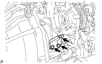
| 22. INSTALL VACUUM SWITCHING VALVE BRACKET |
 |
Install the bracket with the 2 bolts.
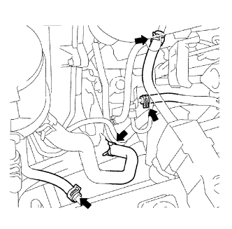
Connect the vacuum hose at the 3 points as shown in the illustration.
Connect the 2 connectors.
| 23. INSTALL MANIFOLD STAY |
 |
Install the stay with the 2 bolts.
| 24. INSTALL GLOW PLUG ASSEMBLY |
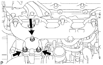
| 25. INSTALL WATER OUTLET |
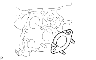 |
Install a new gasket to the cylinder head, as shown in the illustration.
 |
Install the water outlet with the 2 bolts.
| 26. INSTALL THERMOSTAT |
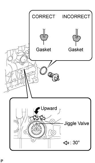 |
Install a new gasket to the thermostat.
Insert the thermostat into the cylinder block with the jiggle valve facing straight upward.
| 27. INSTALL NO. 1 COMPRESSOR MOUNTING BRACKET |
Install the bracket with the 4 bolts.
| 28. INSTALL NO. 1 CHARGE AIR COOLER SUPPORT BRACKET |
Install the bracket with the 2 bolts.
| 29. INSTALL NO. 2 CHARGE AIR COOLER SUPPORT BRACKET |
Install the bracket with the 2 bolts.
| 30. INSTALL V-RIBBED BELT TENSIONER ASSEMBLY |
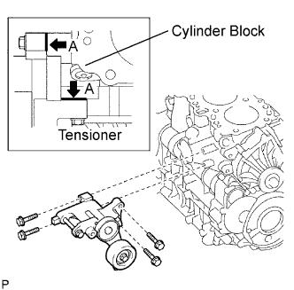 |
Install the tensioner with the 4 bolts.
| 31. INSTALL GENERATOR ASSEMBLY |
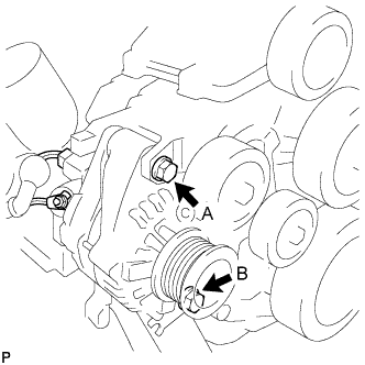 |
Install the generator and adjusting bar with the 2 bolts.
Install the generator wire with the nut.
Connect the generator connector.
| 32. INSTALL GENERATOR BRACKET |
| 33. INSTALL EXHAUST MANIFOLD |
 |
Install a new gasket, manifold, 4 new collars and 8 spacers to the cylinder head with 8 new nuts.
| 34. INSTALL TURBOCHARGER STAY |
 |
Temporarily install a new gasket and the turbocharger with 3 new nuts.
Temporarily install the turbo oil pipe.
Install a new gasket and the oil pipe with the 2 nuts, but only loosely install the nuts.
Install a new gasket and the oil pipe with the 2 bolts, but only loosely install the bolts.
Install a new gasket and the oil pipe with the union bolt, but only loosely install the union bolt.
 |
Temporarily install the turbocharger stay with the 3 bolts.
Tighten the 3 nuts of the turbocharger.
Tighten the 2 nuts and 2 bolts of the oil pipe, and the union bolt.
Tighten the 3 bolts of the turbocharger stay.
| 35. INSTALL TURBO OIL INLET PIPE SUB-ASSEMBLY |
| 36. INSTALL TURBINE OUTLET ELBOW |
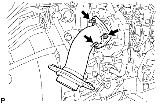 |
Install a new gasket and the outlet elbow with the 3 nuts.
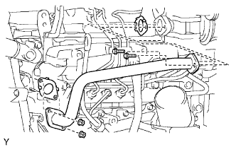
| 37. INSTALL NO. 1 TURBO WATER HOSE |
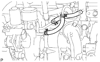 |
Connect the 2 hoses to the 2 tubes.
Move the 2 clamps to the locations where the hoses and tubes are connected.
| 38. INSTALL NO. 1 TURBO INSULATOR |
 |
Temporarily install the turbo insulator with the bolt.
| 39. INSTALL VENTILATION PIPE |
| 40. CONNECT VENTILATION HOSE |
| 41. INSTALL CAMSHAFT TIMING PULLEY |
 |
Install the camshaft timing pulley.
Fasten the bolt of the camshaft timing pulley by holding the camshaft with a wrench.
| 42. INSTALL CRANKSHAFT PULLEY |
 |
Align the pulley set key with the key groove of the pulley.
Using SST, install the pulley bolt.
| 43. INSTALL TIMING BELT |
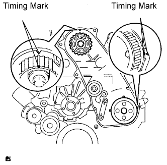 |
Check that the timing marks are aligned as shown in the illustration.
Using a 10 mm hexagon wrench, install the washer and timing belt idler pulley with the bolt.
Check that the idler pulley moves smoothly.
If it does not move smoothly, check the idler sub-assembly and washer.
Install the timing belt to the pump drive shaft pulley, camshaft timing pulley and No. 1 timing belt idler in sequence.
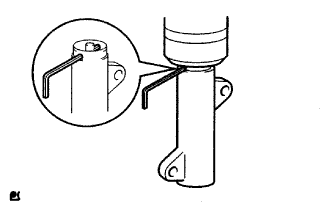 |
Place the tensioner upright. Then set the press to the top of the tensioner.
Using a press, slowly push in the push rod using 981 to 9,807 N (100 to 1,000 kgf, 220 to 2,205 lbf) of force.
Align the holes of the push rod and housing. Then pass a 1.27 mm hexagon wrench through the holes to keep the setting position of the push rod.
Install the timing belt tensioner with the 2 bolts while pushing the idler pulley toward the timing belt.
Tighten the 2 bolts.
 |
Remove the 1.5 mm hexagon wrench from the tensioner.
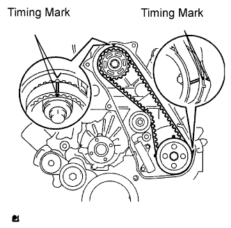 |
Turn the crankshaft clockwise 720° and check that the timing marks are aligned as shown in the illustration.
| 44. INSTALL NO. 1 TIMING BELT COVER |
Install the timing belt cover with the 6 bolts.
Install the wire harness clamp.
Install the water hose clamp with the bolt.
| 45. INSTALL ENGINE WIRE |
Connect the engine wire to the engine.
| 46. REMOVE ENGINE STAND |
| 47. INSTALL ENGINE ASSEMBLY |
 |
Attach the chain block and engine sling device to the engine hangers.
Slowly lower the engine into the engine compartment.
Install the engine mounting bracket with the 4 bolts and 4 nuts.
Remove the 2 engine hangers.
| 48. INSTALL REAR END PLATE |
Install the end plate with the bolt.
| 49. INSTALL FLYWHEEL SUB-ASSEMBLY (for Manual Transmission) |
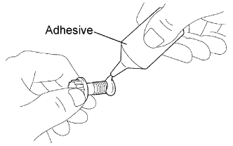 |
Clean the bolt and its hole.
Apply adhesive to 2 or 3 threads of the bolt end.
 |
Using SST, hold the crankshaft.
Install the flywheel on the crankshaft.
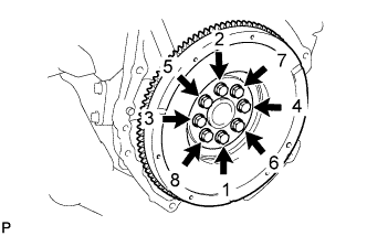 |
Uniformly install and tighten the 8 bolts in the sequence shown in the illustration.
| 50. INSTALL DRIVE PLATE & RING GEAR SUB-ASSEMBLY (for Automatic Transmission) |
|
Clean the bolt and its hole.
Apply adhesive to 2 or 3 threads of the bolt end.
|
Using SST, hold the crankshaft.
Install the flywheel, drive plate and drive plate spacer on the crankshaft.
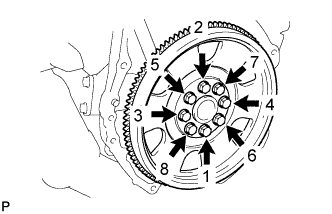 |
Uniformly install and tighten the 8 bolts in the sequence shown in the illustration.
| 51. INSTALL CLUTCH DISC ASSEMBLY (for Manual Transmission) |
 |
Insert SST into the clutch disc. Then insert the SST (together with the clutch disc) into the flywheel.
| 52. INSTALL CLUTCH COVER ASSEMBLY (for Manual Transmission) |
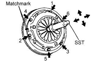 |
Align the matchmarks on the clutch cover and flywheel.
Tighten the 6 bolts as described below.
Determine the first bolt to be tightened by choosing the bolt closest to the knock pin.
Uniformly tighten the 6 bolts in diametrically opposite pairs relative to the position of the first bolt. Use the illustration as a reference.
Lightly move SST up and down, and right and left.
Check that the disc is in the center, and then tighten the bolts.
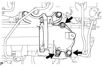
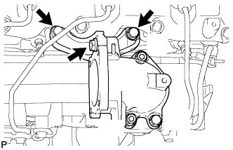
| 53. INSTALL COOLER COMPRESSOR ASSEMBLY |
Install the compressor with the 4 bolts.
| 54. CONNECT HOSES AND CONNECTORS |
 |
Using SST, install the pressure feed tube.
 |
Connect the 2 fuel hoses.
Connect the vacuum pump hose.
Connect the oil reservoir to pump hose.
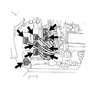 |
Connect the 4WD control ECU connector.
Connect the turbo motor driver connector.
Connect the 3 TCM connectors.
Connect the 4 ECM connectors.
 |
Connect the 2 injector driver connectors.
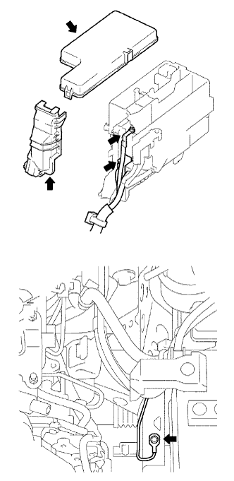 |
Install the ground cable with the bolt.
Connect the 2 engine room junction block connectors.
Install the engine room J/B wire with the nut.
Install the engine room relay block cover (side).
Install the engine room relay block cover (upper).
| 55. INSTALL TRANSMISSION ASSEMBLY (for Manual Transmission) |
Install the transmission assembly (Click here).
| 56. INSTALL TRANSMISSION ASSEMBLY (for Automatic Transmission) |
Install the transmission assembly (Click here).
| 57. INSTALL PROPELLER SHAFT ASSEMBLY |
Front Side:
Install the propeller shaft assembly (Click here).
Rear Side:
Install the propeller shaft assembly (Click here).
| 58. INSTALL FRONT EXHAUST PIPE |
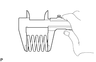 |
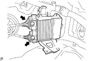
Using a vernier caliper, measure the free length of the compression spring.
Install the front pipe to the pipe support.
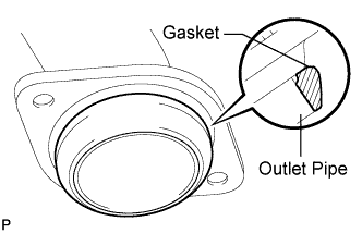 |
Install a new gasket to the outlet pipe.
Install the front pipe with the 2 compression springs and 2 bolts. Alternately tighten the bolts in several passes.
| 59. INSTALL STARTER ASSEMBLY |
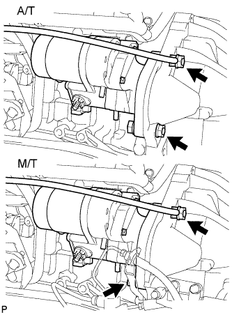 |
A/T:
Install the starter and ground cable with the 2 nuts and bolt.
M/T:
Install the starter and ground cable with the nut and bolt.
Install the starter wire to terminal 30 with the nut.
Connect the starter connector.
A/T:
Install the A/T oil dipstick with the 2 bolts.
M/T:
Install the clutch release cylinder.
| 60. INSTALL CHARGE AIR COOLER ASSEMBLY WITH INTAKE AIR CONNECTOR |
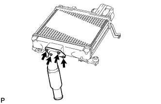 |
Install a new gasket and the intake air connector with the 4 bolts.
 |
Using a 22 mm deep socket wrench, install a new gasket and the IAT sensor.
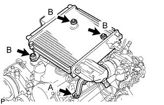 |
Install the CAC with the 4 bolts.
Tighten the 4 hose clamps of the No. 1 and No. 2 air hose.
Connect the diesel turbo IAT sensor connector.
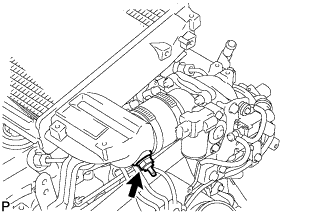
| 61. INSTALL NO. 1 ENGINE COVER SUB-ASSEMBLY |
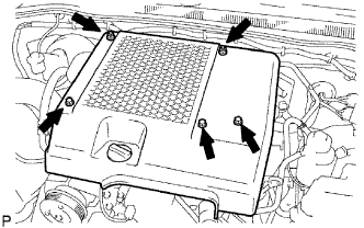 |
Install the engine cover with the 3 bolts and 2 nuts.
| 62. INSTALL RADIATOR ASSEMBLY |
Install the radiator assembly (Click here).
| 63. INSTALL AIR CLEANER ASSEMBLY |
Install the cleaner with the 2 bolts.
Connect the connector to the MAF meter.
Connect the hose clamp.
| 64. INSTALL BATTERY AND BATTERY TRAY |
| 65. INSTALL BATTERY BRACKET |
| 66. ADD TRANSMISSION OIL (for Manual Transmission) |
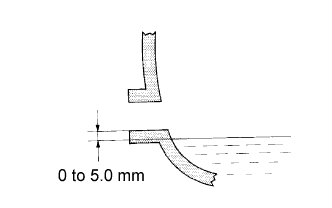 |
Stop the vehicle on a level surface.
Remove the filer plug and gasket.
Check that the oil level is between 0 to 5 mm (0 to 0.20 in.) from the bottom lip of the filler plug opening.
If the result is not as specified, add transmission oil.
Check for oil leakage when the oil level is low.
If leakage is found, repair the area necessary to stop the leak. Replace damaged parts as necessary.
Install a new gasket and the filler plug.
| 67. ADD TRANSMISSION FLUID |
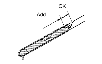 |
Park the vehicle on a level surface and set the parking brake.
With the engine idling and the brake pedal depressed, move the shift lever into all positions from P to L. Then return it to P.
Pull out the dipstick and wipe it clean.
Push it back fully into the pipe.
Pull it out and check that the fluid level is in the HOT range.
If there are leaks, it is necessary to repair or replace O-rings, FIPG, oil seals, plugs or other parts.
| 68. ADD ENGINE COOLANT |
Tighten the radiator drain cock plug by hand.
Tighten the cylinder block drain cock plug.
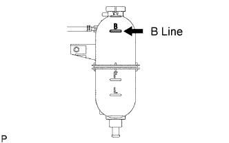 |
Fill the radiator with TOYOTA Super Long Life Coolant (SLLC) to the reservoir tank's B line.
| Item | Specified Condition |
| A/T | 11.1 liters (11.7 US qts, 9.8 lmp. qts) |
| M/T | 9.8 liters (10.4 US qts, 8.6 lmp. qts) |
Press the inlet and outlet radiator hoses several times by hand, and then check the level of the coolant.
If the coolant level drops below the B line, add TOYOTA SLLC to the B line.
Install the radiator reservoir cap.
 |
Using a wrench, install the vent plug.
Bleed air from the cooling system.
Warm up the engine until the thermostat opens. While the thermostat is open, circulate the coolant for several minutes.
Maintain the engine speed at 2,000 to 2,500 rpm.
Press the inlet and outlet radiator hoses several times by hand to bleed air.
Stop the engine and wait until the coolant cools down to ambient temperature.
 |
After the coolant cools down, check that the coolant level is at the F line.
If the coolant level is below the F line, add TOYOTA SLLC to the F line.
| 69. ADD FUEL |
| 70. TIGHTEN FUEL TANK CAP ASSEMBLY |
| 71. ADD ENGINE OIL |
Wipe the oil pan and drain plug before installing the plug.
Install a new gasket and the drain plug.
Add new oil.
| Item | Capacity |
| Drain and refill with oil filter change | 6.9 liters (7.3 US qts, 6.1 Imp. qts) |
| Drain and refill without oil filter change | 6.6 liters (7.0 US qts, 5.8 Imp. qts) |
| Dry fill | 7.4 liters (7.8 US qts, 6.5 Imp. qts) |
Install the oil filler cap.
| 72. INSTALL HOOD SUB-ASSEMBLY |
Install the hood with the 4 bolts.
Connect the washer nozzle hose.
Adjust the hood.
| 73. BLEED AIR FROM FUEL SYSTEM |
 |
Using the hand pump, bleed air from the fuel system until pumping becomes difficult.
| 74. CONNECT CABLE TO NEGATIVE BATTERY TERMINAL |
| 75. PERFORM INITIALIZATION |
Perform initialization (see page ).
| 76. CHECK FOR ENGINE OIL LEAKS |
| 77. CHECK FOR ENGINE COOLANT LEAKS |
| 78. CHECK FOR EXHAUST GAS LEAKS |
| 79. CHECK FOR FUEL LEAKS |
| 80. CHECK ENGINE IDLE SPEED AND MAXIMUM SPEED |
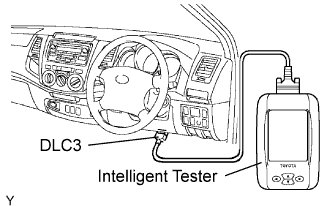 |
Connect the intelligent tester to the DLC3.
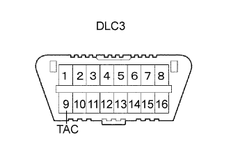 |
If a tester is not available, connect a tester probe of a tachometer to terminal 9 (TAC) of the DLC3 with SST.
Inspect the idle speed.
Start the engine and measure the idle speed.
Inspect the maximum speed.
Start the engine.
Fully depress the accelerator pedal.
Measure the maximum speed.
If the tester probe of the tachometer is connected to the DLC3, disconnect the tester probe with SST from terminal 9 of the DLC3.
Disconnect the intelligent tester from the DLC3.
| 81. CHECK OIL LEVEL |
| 82. INSTALL NO. 2 ENGINE UNDER COVER (for 4WD) |
Install the under cover with the 2 bolts.
| 83. INSTALL NO. 1 ENGINE UNDER COVER (for 4WD) |
Install the under cover with the 2 bolts.
