CYLINDER HEAD > REMOVAL |
| 1. DISCONNECT CABLE FROM NEGATIVE BATTERY TERMINAL |
| 2. DRAIN ENGINE OIL |
Remove the oil filter cap.
Remove the oil drain plug, and drain the engine oil from the oil pan.
| 3. LOOSEN FUEL TANK CAP ASSEMBLY |
| 4. DRAIN FUEL |
| 5. REMOVE FRONT EXHAUST PIPE ASSEMBLY |
Remove the 2 bolts and 2 compression springs.
Disconnect the front pipe from the outlet pipe and remove the gasket.
Remove the front pipe from the pipe support.
| 6. REMOVE NO. 1 ENGINE COVER SUB-ASSEMBLY |
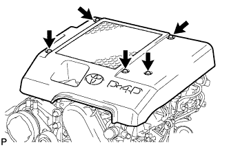 |
Remove the 3 bolts, 2 nuts and cover.
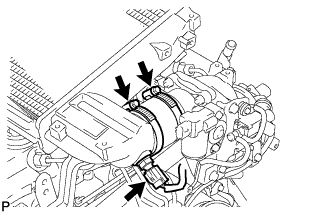
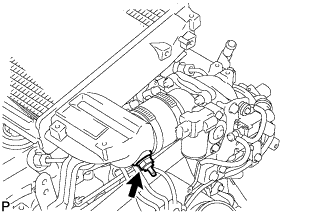
| 7. REMOVE CHARGE AIR COOLER ASSEMBLY WITH INTAKE AIR CONNECTOR |
 |
Disconnect the diesel turbo IAT sensor connector.
Loosen the 2 hose clamps of the No. 1 air hose.
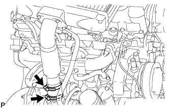 |
Loosen the 2 hose clamps of the No. 2 air hose.
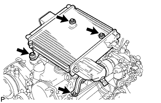 |
Remove the 4 bolts and CAC.
 |
Using a 22 mm deep socket wrench, remove the IAT sensor.
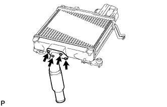 |
Remove the 4 bolts, intake air connector and gasket.
| 8. REMOVE AIR CLEANER ASSEMBLY |
Disconnect the MAF meter connector.
Loosen the hose clamp.
Remove the 3 bolts and air cleaner.
| 9. REMOVE VENTILATION PIPE |
| 10. REMOVE FAN SHROUD |
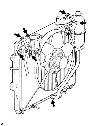 |
Remove the 3 bolts and oil reservoir.
Disconnect the No. 1 and No. 2 water by-pass hoses from the tank upper and lower.
Remove the 2 bolts and radiator reservoir.
Loosen the 4 nuts holding the fluid coupling fan.
Remove the drive belt (Click here).
Remove the 2 bolts holding the fan shroud.
Remove the 4 nuts of the fluid coupling fan, and then remove the shroud together with the coupling fan.
Remove the fan pulley from the water pump.
| 11. REMOVE FAN PULLEY |
Remove the fan pulley.
| 12. DISCONNECT COOLER COMPRESSOR ASSEMBLY |
Remove the 4 bolts and disconnect the cooler compressor.
| 13. REMOVE NO. 1 COMPRESSOR MOUNTING BRACKET |
Remove the 4 bolts and mounting bracket.
| 14. REMOVE EXHAUST MANIFOLD |
 |
Remove the 8 nuts and exhaust manifold w/ turbocharger as shown in the illustration.
| 15. REMOVE MANIFOLD STAY |
 |
Remove the 2 bolts and stay.
| 16. DISCONNECT WIRE HARNESS |
| 17. REMOVE INJECTION PIPE |
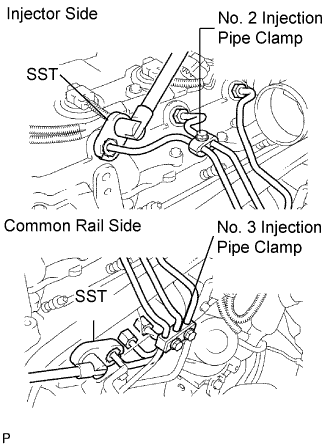 |
Remove the 2 nuts and No. 3 injection pipe clamp.
Remove the bolt and No. 2 injection pipe clamp.
Using SST, loosen the union nuts and remove the No. 1, No. 2 and No. 3 injection pipes.
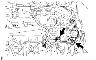 |
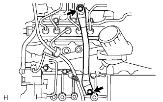
Remove the 2 bolts and disconnect the 2 injection pipe clamps.
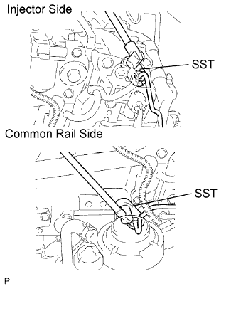 |
Using SST, loosen the union nuts and remove the No. 4 injection pipe.
| 18. REMOVE NO. 2 NOZZLE LEAKAGE PIPE ASSEMBLY |
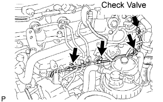 |
Disconnect the 2 fuel hoses.
Remove the check valve, 3 bolts, leakage pipe and gasket.
| 19. REMOVE EGR VALVE ASSEMBLY |
Remove the EGR valve and gasket.
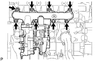
| 20. REMOVE INTAKE MANIFOLD |
 |
Remove the 4 bolts, 2 nuts, manifold and gasket.
| 21. REMOVE NO. 1 TIMING BELT COVER |
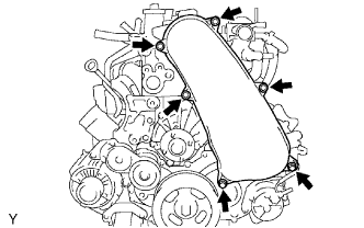 |
Remove the bolt and water hose clamp.
Remove the wire harness clamp.
Remove the 6 bolts and timing belt cover.
| 22. REMOVE TIMING BELT |
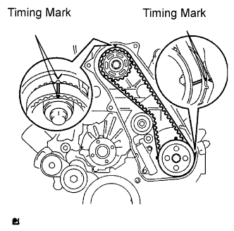 |
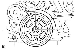
Turn the crankshaft clockwise and align the timing marks as shown in the illustration.
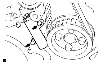 |
Uniformly loosen the 2 bolts and remove the timing belt tensioner.
Remove the timing belt.
Using a 10 mm hexagon wrench, remove the bolt, timing belt idler and washer.
| 23. REMOVE CYLINDER HEAD COVER SUB-ASSEMBLY |
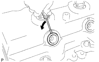 |
Using a small screwdriver, remove the holder seal by prying the portion between the holder seal and the cutout part of the cylinder head.
 |
Remove the 10 bolts, 2 nuts, cylinder head cover and gasket.
| 24. REMOVE CAMSHAFT TIMING PULLEY |
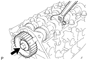 |
Remove the bolt of the camshaft timing pulley by holding the camshaft with a wrench.
Remove the camshaft timing pulley.
| 25. REMOVE NO. 1 TIMING BELT IDLER SUB-ASSEMBLY |
| 26. REMOVE NO. 2 TIMING BELT COVER |
Remove the 4 bolts, nuts and timing belt cover.
| 27. REMOVE INJECTOR ASSEMBLY |
 |
Remove the union bolt, 4 hollow screws, 5 gaskets and nozzle leakage pipe.
 |
Remove the 4 bolts, 4 washers, 4 nozzle holder clamps and 4 injectors.
Remove the O-ring and back-up ring from the injector.
Remove the 4 injection nozzle sheets from the cylinder head.
| 28. REMOVE CAMSHAFT |
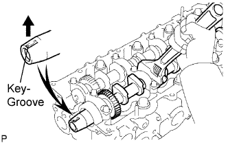 |
Face the key groove of the camshaft upward by turning the camshaft with a wrench.
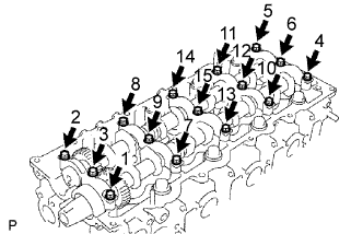 |
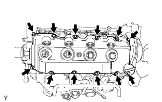
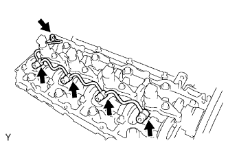
Uniformly loosen the 15 bearing cap bolts in several passes in the sequence shown in the illustration.
Remove the 5 bearing caps, oil seal and 2 camshafts.
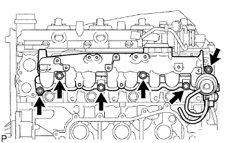
| 29. REMOVE CYLINDER HEAD SUB-ASSEMBLY |
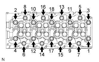 |
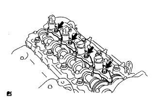
Uniformly loosen and remove the 18 cylinder head bolts in several passes in the sequence shown in the illustration.
Lift the cylinder head from the dowels on the cylinder block, and place the cylinder head on wooden blocks on a bench.
| 30. REMOVE CYLINDER HEAD GASKET |
