CYLINDER HEAD > INSTALLATION |
| 1. INSTALL CYLINDER HEAD GASKET |
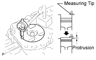 |
Find where the piston head protrudes most by slowly turning the crankshaft clockwise and counterclockwise.
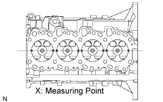 |
Measure the piston protrusion of each cylinder at 2 points as shown in the illustration.
For the piston protrusion value of each cylinder, use the average of the 2 measurements of each cylinder.
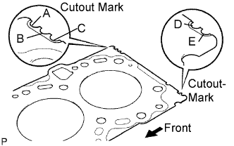 |
Select a new cylinder head gasket.
| Mark | Thickness |
| A | 0.80 to 0.90 mm (0.0315 to 0.0354 in.) |
| B | 0.85 to 0.95 mm (0.0335 to 0.0374 in.) |
| C | 0.90 to 1.00 mm (0.0354 to 0.0394 in.) |
| D | 0.95 to 1.05 mm (0.0374 to 0.0413 in.) |
| E | 1.00 to 1.10 mm (0.0394 to 0.0433 in.) |
Select the largest piston protrusion value from the measurements made. Then select a new appropriate gasket according to the table below.
| Gasket Size | Piston Protrusion |
| Use A | 0.005 to 0.054 mm (0.0002 to 0.0021 in.) |
| Use B | 0.055 to 0.104 mm (0.0022 to 0.0041 in.) |
| Use C | 0.105 to 0.154 mm (0.0041 to 0.0061 in.) |
| Use D | 0.155 to 0.204 mm (0.0061 to 0.0080 in.) |
| Use E | 0.205 to 0.255 mm (0.0081 to 0.0100 in.) |
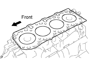 |
Place the cylinder head on the cylinder block.
Place the cylinder head gasket on the cylinder block.
Place the cylinder head on the cylinder head gasket.
| 2. INSTALL CYLINDER HEAD SUB-ASSEMBLY |
 |
Apply a light coat of engine oil on the threads and under the heads of the cylinder head bolts.
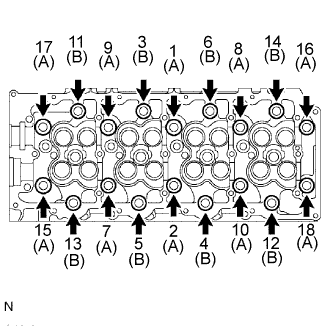
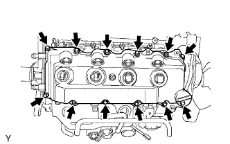
Install and uniformly tighten the 18 cylinder head bolts, in several passes in the sequence shown in the illustration.
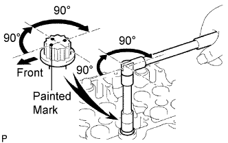 |
Mark the front of the cylinder head bolt with paint.
Further tighten the cylinder head bolts by 90° in the sequence shown in the illustration above.
Finally, tighten the cylinder head bolts by an additional 90°.
Check that the painted mark is now facing rearward.
| 3. INSTALL CAMSHAFT |
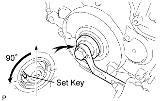 |
Using the crankshaft pulley bolt, set the No. 1 cylinder to 90° BTDC/compression.
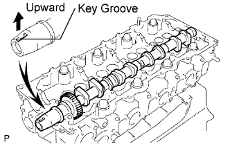 |
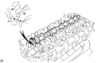
Install the camshaft.
Apply MP grease to the thrust portion of the camshaft.
Place the camshaft on the cylinder head, facing the key groove upward.
 |
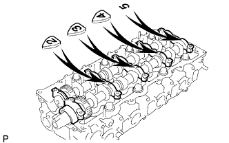
Align the timing marks (1 dot mark) of the camshaft drive and driven main gears, and set the No. 2 camshaft in place.
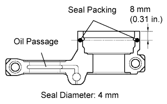 |
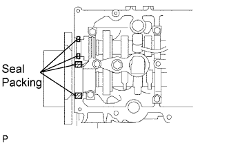
Remove any old packing (FIPG) material from the camshaft bearing cap.
Apply seal packing to the specified areas shown in the illustration.
 |
Install the 5 bearing caps in their proper locations.
 |
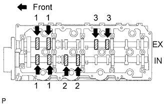
Apply a light coat of engine oil on the threads and under the heads of the bearing cap bolts.
Install and uniformly tighten the 10 bearing cap bolts in several passes in the sequence shown in the illustration.
Install the camshaft oil seal.
| 4. INSPECT VALVE CLEARANCE |
 |
Check only the valves indicated.
Using a feeler gauge, measure the clearance between the valve lifter and camshaft.
| Intake | Exhaust |
| 0.20 to 0.30 mm (0.008 to 0.012 in.) | 0.35 to 0.45 mm (0.014 to 0.018 in.) |
Turn the crankshaft 360° to set the No. 4 cylinder to TDC / compression.
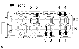 |
Check only the valves indicated.
Using a feeler gauge, measure the clearance between the valve lifter and camshaft.
| Intake | Exhaust |
| 0.20 to 0.30 mm (0.008 to 0.012 in.) | 0.35 to 0.45 mm (0.014 to 0.018 in.) |
| 5. ADJUST VALVE CLEARANCE |
Drain coolant.
Remove the fan shroud.
Remove the No. 1 timing belt cover.
Remove the timing belt.
Remove the camshaft timing pulley.
Remove the No. 1 timing belt idler.
Remove the No. 2 timing belt cover.
Remove the camshafts.
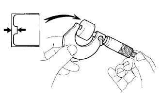 |
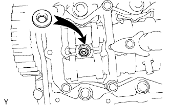
Remove the valve lifters.
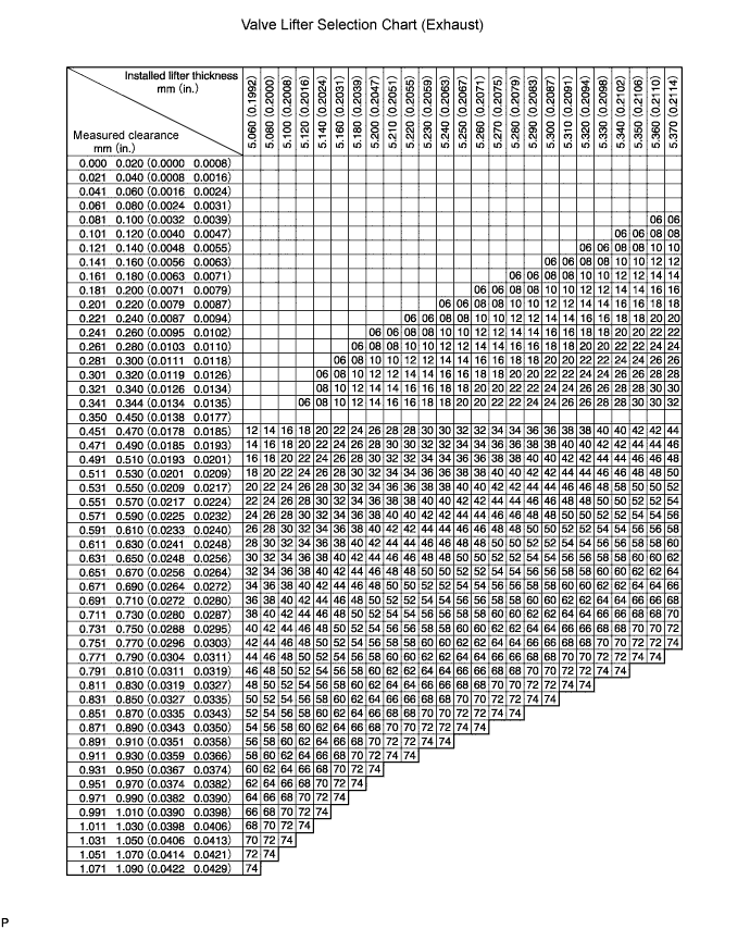
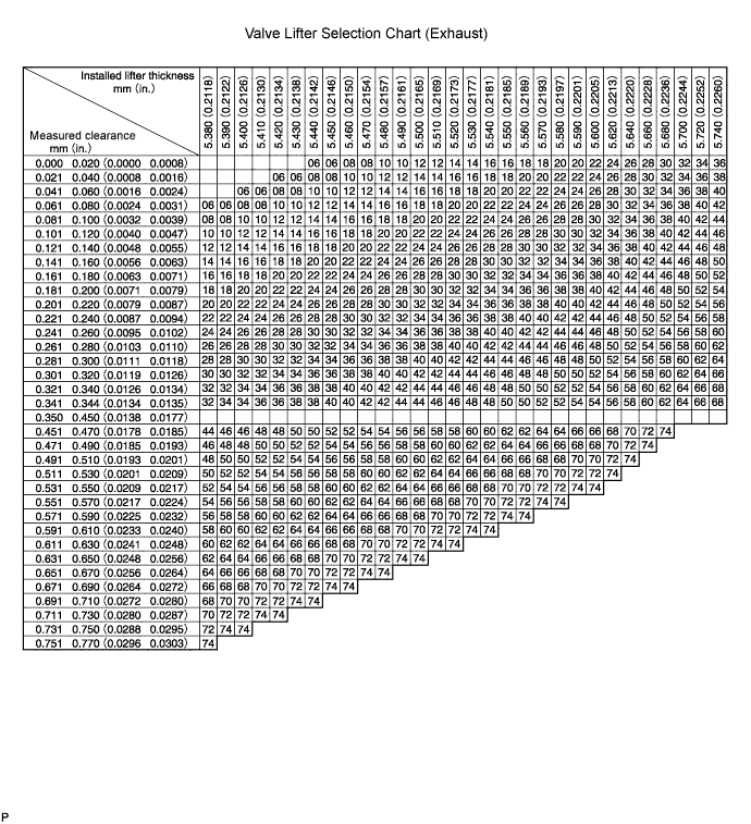
Using a micrometer, measure the thickness of the removed lifter.
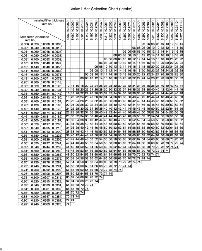
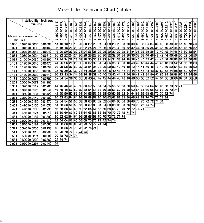
Calculate the thickness of a new lifter so that the valve clearance comes within the specified value.
| A | B | C |
| Thickness of new lifter | Thickness of used lifter | Measured valve clearance |
Select a new lifter with a thickness as close as possible to the calculated values.
Install the selected valve lifter.
| Shim No. | Thickness | Shim No. | Thickness | Shim No. | Thickness |
| 06 | 5.060 (0.1992) | 30 | 5.300 (0.2087) | 54 | 5.540 (0.2181) |
| 08 | 5.080 (0.2000) | 32 | 5.320 (0.2094) | 56 | 5.560 (0.2189) |
| 10 | 5.100 (0.2008) | 34 | 5.340 (0.2102) | 58 | 5.580 (0.2197) |
| 12 | 5.120 (0.2016) | 36 | 5.360 (0.2110) | 60 | 5.600 (0.2205) |
| 14 | 5.140 (0.2024) | 38 | 5.380 (0.2118) | 62 | 5.620 (0.2213) |
| 16 | 5.160 (0.2031) | 40 | 5.400 (0.2126) | 64 | 5.640 (0.2220) |
| 18 | 5.180 (0.2039) | 42 | 5.420 (0.2134) | 66 | 5.660 (0.2228) |
| 20 | 5.200 (0.2047) | 44 | 5.440 (0.2142) | 68 | 5.680 (0.2236) |
| 22 | 5.220 (0.2055) | 46 | 5.460 (0.2150) | 70 | 5.700 (0.2244) |
| 24 | 5.240 (0.2063) | 48 | 5.480 (0.2157) | 72 | 5.720 (0.2252) |
| 26 | 5.260 (0.2071) | 50 | 5.500 (0.2165) | 74 | 5.740 (0.2260) |
| 28 | 5.280 (0.2079) | 52 | 5.520 (0.2173) | - | - |
Install the camshaft.
Install the No. 2 timing belt cover.
Install the No. 1 timing belt idler.
Install the camshaft timing pulley.
Install the timing belt.
Install the No. 1 timing belt cover.
Install the fan shroud.
Add engine coolant.
| 6. INSTALL INJECTOR ASSEMBLY |
 |
Install 4 new injection nozzle sheets to the cylinder head.
Apply a light amount of clean engine oil to 4 new O-rings.
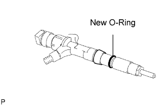 |
Install the O-ring to each injector as shown in the illustration.
Insert the 4 injectors into the cylinder head.
Register injector compensation code (when replacing with a new injector).
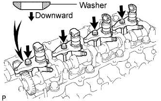 |
Temporarily install 4 new washers and the 4 nozzle clamps with the 4 clamp bolts.
Temporarily install the 4 injection pipes with the union nuts.
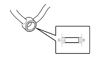 |
Check the nozzle leakage pipe. Check that there are no scratches or dents on the 5 union seal surfaces.
If scratches or dents are present, replace the nozzle leakage pipe.
 |
Set the leakage pipe and 5 new gaskets in place.
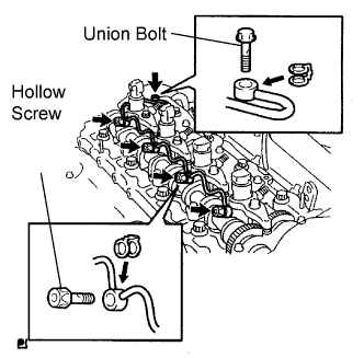
Apply a light amount of oil to the 4 hollow screws and union bolt.
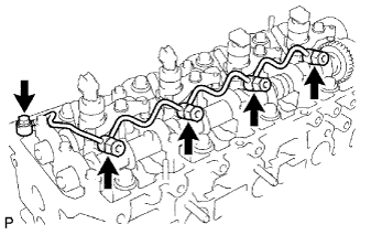 |
Temporarily install the leakage pipe with the 4 hollow screws and union bolt.
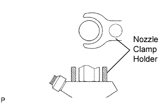
Tighten the 4 holder clamp bolts.
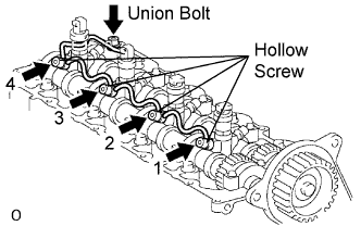 |
Tighten the 4 hollow screws in order from 1 to 4.
Tighten the union bolt.
Remove the 4 injection pipes.
| 7. CHECK FOR FUEL LEAKS |
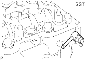 |
Check that there are no leaks from the nozzle leakage pipe connection.
Install the gasket and No. 2 nozzle leakage pipe to the cylinder head with SST (check valve).
Apply a light amount of soapy water (or other fluid for detecting fuel leakage) on the nozzle leakage pipe connection.
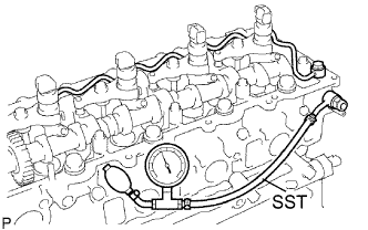 |
Install SST (turbocharger pressure gauge) to the fuel return side of the leakage pipe, and maintain 250 kPa (2.5 kgf/cm2, 35.5 psi) of pressure for 60 seconds to check that no bubbles form.
After checking for fuel leaks, wipe off the soapy water from the leakage pipe connection.
Remove SST, No. 2 nozzle leakage pipe and gasket.
| 8. INSTALL NO. 2 TIMING BELT COVER |
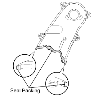 |
Apply seal packing (FIPG) to the specified areas shown in the illustration.
Install the No. 2 timing belt cover with the 4 bolts and nut.
| 9. INSTALL CAMSHAFT TIMING PULLEY |
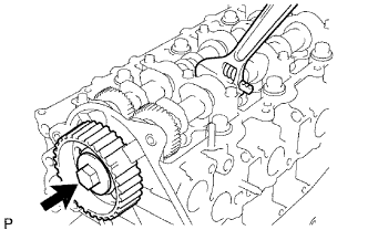 |
Install the camshaft timing pulley.
Fasten the bolt of the camshaft timing pulley by holding the camshaft with a wrench.
| 10. INSTALL CYLINDER HEAD COVER SUB-ASSEMBLY |
 |
Remove any old seal packing (FIPG) material from the cylinder head.
Apply seal packing to the specific areas shown in the illustration.
 |
Install the gasket and cylinder head cover with the 10 bolts and 2 nuts.
Install 4 new nozzle holder seals.
| 11. INSTALL NO. 1 TIMING BELT IDLER SUB-ASSEMBLY |
| 12. INSTALL TIMING BELT |
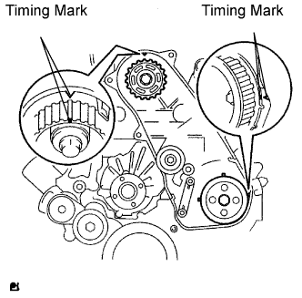 |
Check that the timing marks are aligned as shown in the illustration.
Using a 10 mm hexagon wrench, install the washer and timing belt idler pulley with the bolt.
Check that the idler pulley moves smoothly.
If it does not move smoothly, check the idler sub-assembly and washer.
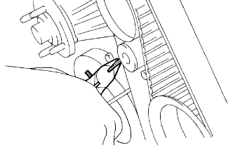
Install the timing belt to the pump drive shaft pulley, camshaft timing pulley and No. 1 timing belt idler in sequence.
 |
Place the tensioner upright. Then set the press to the top of the tensioner.
Using a press, slowly push in the push rod using 981 to 9,807 N (100 to 1,000 kgf, 220 to 2,205 lbf) of force.
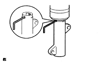
Align the holes of the push rod and housing. Then pass a 1.27 mm hexagon wrench through the holes to keep the setting position of the push rod.
Install the timing belt tensioner with the 2 bolts while pushing the idler pulley toward the timing belt.
Tighten the 2 bolts.
 |
Remove the 1.5 mm hexagon wrench from the tensioner.
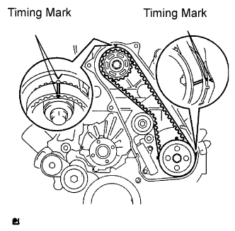 |
Turn the crankshaft clockwise 720° and check that the timing marks are aligned as shown in the illustration.
| 13. INSTALL NO. 1 TIMING BELT COVER |
Install the timing belt cover with the 6 bolts.
Install the wire harness clamp.
Install the water hose clamp with the bolt.
| 14. INSTALL EGR VALVE ASSEMBLY |
Install a new gasket and the EGR valve.
| 15. INSTALL NO. 2 NOZZLE LEAKAGE PIPE ASSEMBLY |
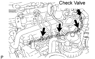 |
Temporarily install the leakage pipe with the 3 bolts.
Temporarily install a new gasket with the check valve.
Fully tighten the 3 bolts and check valve.
Connect the 2 fuel hoses.
| 16. INSTALL INJECTION PIPE |
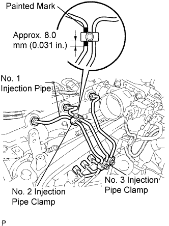 |
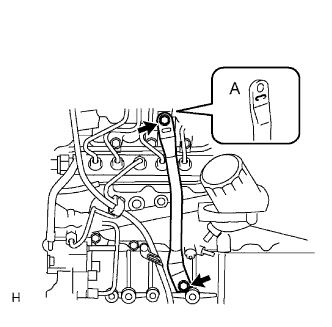
Temporarily install the No. 1, No. 2 and No. 3 injection pipes with the union nuts.
Install the No. 2 and No. 3 injection pipe clamps with the bolt and 2 nuts, as shown in the illustration.
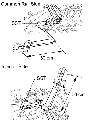 |
Using SST, tighten the injection pipe union nuts on the common rail side.
Using SST, tighten the injection pipe union nuts on the injector side.
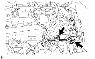 |
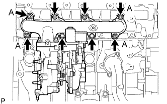
Temporarily install the No. 4 injection pipe with the union nuts.
Install 2 new injection pipe clamps with the 2 bolts.
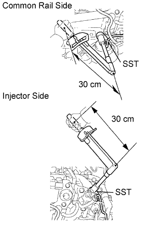 |
Using SST, tighten the injection pipe union nuts on the common rail side.
Using SST, tighten the injection pipe union nuts on the injector side.
| 17. CONNECT WIRE HARNESS |
| 18. INSTALL MANIFOLD STAY |
 |
Install the stay with the 2 bolts.
| 19. INSTALL EXHAUST MANIFOLD |
 |
Install a new gasket, manifold, 4 new collars and 8 spacers to the cylinder head with 8 new nuts.
| 20. INSTALL NO. 1 COMPRESSOR MOUNTING BRACKET |
Install the bracket with the 4 bolts.
| 21. INSTALL COOLER COMPRESSOR ASSEMBLY |
Install the compressor with the 4 bolts.
| 22. INSTALL FAN PULLEY |
Install the fan pulley.
| 23. INSTALL FAN SHROUD |
Install the fan pulley to the water pump.
Install the shroud together with the coupling fan between the radiator and engine component.
Install the fluid coupling fan to the fan pulley with the 4 nuts.
Tighten the nuts as much as possible by hand.
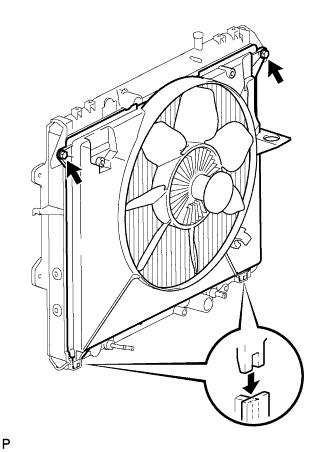 |
Attach the shroud's claws to the radiator.
Install the shroud with the 2 bolts.
Install the drive belt (Click here).
Tighten the 4 nuts of the fluid coupling fan.
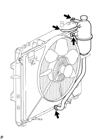 |
Install the radiator reservoir with the 2 bolts.
Connect the No. 1 and No. 2 water by-pass hoses to the tank upper and lower.
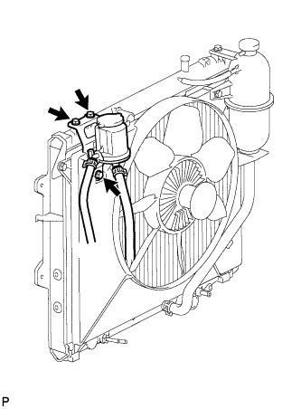 |
Install the oil reservoir with the 3 bolts.
| 24. INSTALL VENTILATION PIPE |
| 25. INSTALL AIR CLEANER ASSEMBLY |
Install the cleaner with the 2 bolts.
Connect the connector to the MAF meter.
Connect the hose clamp.
| 26. INSTALL CHARGE AIR COOLER ASSEMBLY WITH INTAKE AIR CONNECTOR |
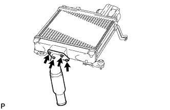 |
Install a new gasket and the intake air connector with the 4 bolts.
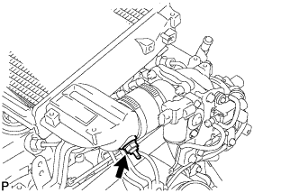 |
Using a 22 mm deep socket wrench, install a new gasket and the IAT sensor.
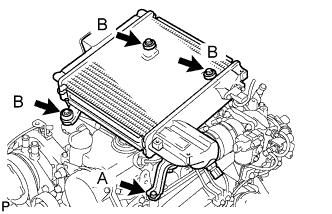 |
Install the CAC with the 4 bolts.
Tighten the 4 hose clamps of the No. 1 and No. 2 air hose.
Connect the diesel turbo IAT sensor connector.
| 27. INSTALL NO. 1 ENGINE COVER SUB-ASSEMBLY |
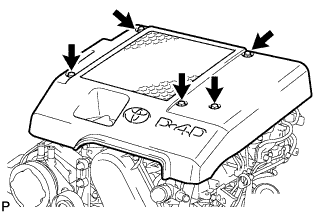 |
Install the cover with the 3 bolts and 2 nuts.
| 28. INSTALL FRONT EXHAUST PIPE ASSEMBLY |
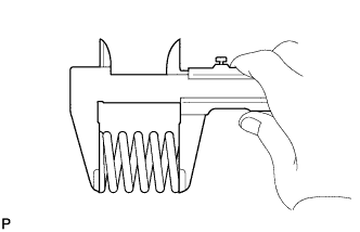 |
Using a vernier caliper, measure the free length of the compression spring.
Install the front pipe to the pipe support.
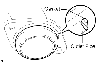 |
Install a new gasket to the outlet pipe.
Install the front pipe with the 2 compression springs and 2 bolts. Alternately tighten the bolts in several passes.
| 29. ADD FUEL |
| 30. TIGHTEN FUEL TANK CAP ASSEMBLY |
| 31. ADD ENGINE OIL |
Wipe the oil pan and drain plug before installing the plug.
Install a new gasket and the drain plug.
Add new oil.
| Item | Capacity |
| Drain and refill with oil filter change | 6.9 liters (7.3 US qts, 6.1 Imp. qts) |
| Drain and refill without oil filter change | 6.6 liters (7.0 US qts, 5.8 Imp. qts) |
| Dry fill | 7.4 liters (7.8 US qts, 6.5 Imp. qts) |
Install the oil filler cap.
| 32. BLEED AIR FROM FUEL SYSTEM |
 |
Using the hand pump, bleed air from the fuel system until pumping becomes difficult.
| 33. CONNECT CABLE TO NEGATIVE BATTERY TERMINAL |
| 34. PERFORM INITIALIZATION |
Perform initialization (Click here).
| 35. CHECK FOR ENGINE OIL LEAKS |
| 36. CHECK FOR FUEL LEAKS |
| 37. CHECK OIL LEVEL |
