VALVE CLEARANCE > ADJUSTMENT |
| 1. DISCONNECT CABLE FROM NEGATIVE BATTERY TERMINAL |
| 2. REMOVE NO. 1 ENGINE COVER SUB-ASSEMBLY |
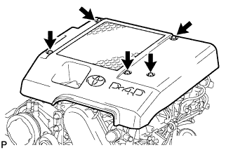 |
Remove the 3 bolts, 2 nuts and cover.
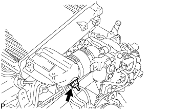
| 3. REMOVE CHARGE AIR COOLER ASSEMBLY WITH INTAKE AIR CONNECTOR |
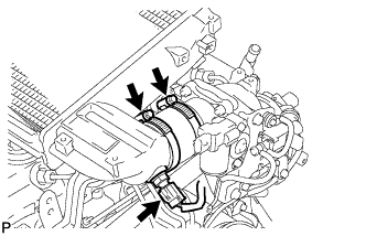 |
Disconnect the diesel turbo IAT sensor connector.
Loosen the 2 hose clamps of the No. 1 air hose.
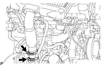 |
Loosen the 2 hose clamps of the No. 2 air hose.
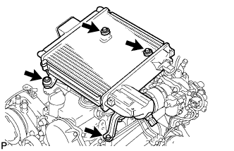 |
Remove the 4 bolts and CAC.
 |
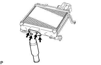
Using a 22 mm deep socket wrench, remove the IAT sensor.
 |
Remove the 4 bolts, intake air connector and gasket.
| 4. LOOSEN FUEL TANK CAP ASSEMBLY |
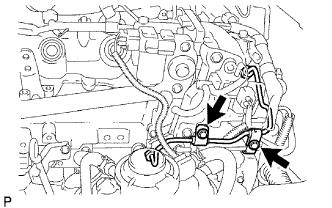
| 5. REMOVE INJECTION PIPE |
 |
Remove the 2 nuts and No. 3 injection pipe clamp.
Remove the bolt and No. 2 injection pipe clamp.
Using SST, loosen the union nuts and remove the No. 1, No. 2 and No. 3 injection pipes.
 |
Remove the 2 bolts and disconnect the 2 injection pipe clamps.
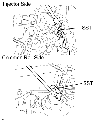 |
Using SST, loosen the union nuts and remove the No. 4 injection pipe.
| 6. REMOVE CYLINDER HEAD COVER SUB-ASSEMBLY |
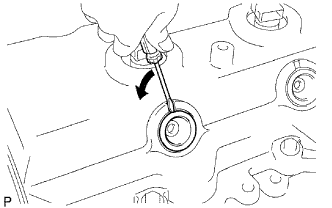 |
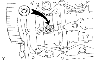
Using a small screwdriver, remove the holder seal by prying the portion between the holder seal and the cutout part of the cylinder head.
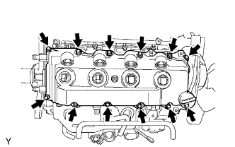 |
Remove the 10 bolts, 2 nuts, cylinder head cover and gasket.
| 7. REMOVE INJECTOR ASSEMBLY |
 |
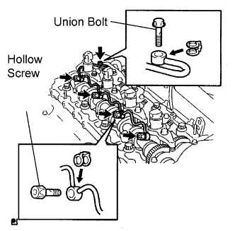
Remove the union bolt, 4 hollow screws, 5 gaskets and nozzle leakage pipe.
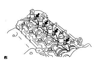 |
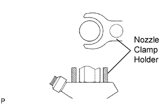
Remove the 4 bolts, 4 washers, 4 nozzle holder clamps and 4 injectors.
Remove the O-ring and back-up ring from the injector.
Remove the 4 injection nozzle sheets from the cylinder head.
| 8. SET NO. 1 CYLINDER TO TDC/COMPRESSION |
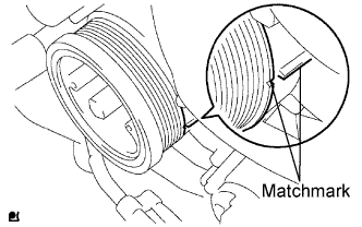 |
Align the matchmarks of the crankshaft pulley and timing gear case cover by rotating the crankshaft clockwise.
| 9. INSPECT VALVE CLEARANCE |
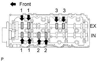 |
Check only the valves indicated.
Using a feeler gauge, measure the clearance between the valve lifter and camshaft.
| Intake | Exhaust |
| 0.20 to 0.30 mm (0.008 to 0.012 in.) | 0.35 to 0.45 mm (0.014 to 0.018 in.) |
Turn the crankshaft 360° to set the No. 4 cylinder to TDC / compression.
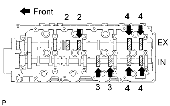 |
Check only the valves indicated.
Using a feeler gauge, measure the clearance between the valve lifter and camshaft.
| Intake | Exhaust |
| 0.20 to 0.30 mm (0.008 to 0.012 in.) | 0.35 to 0.45 mm (0.014 to 0.018 in.) |
| 10. ADJUST VALVE CLEARANCE |
Drain coolant.
Remove the fan shroud.
Remove the No. 1 timing belt cover.
Remove the timing belt.
Remove the camshaft timing pulley.
Remove the No. 1 timing belt idler.
Remove the No. 2 timing belt cover.
Remove the camshafts.
 |
Remove the valve lifters.
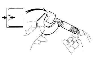
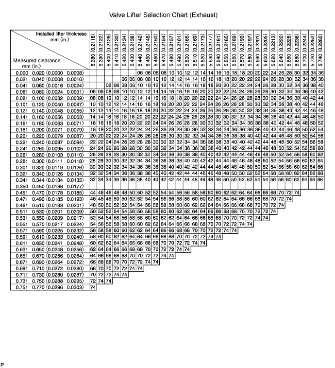
Using a micrometer, measure the thickness of the removed lifter.
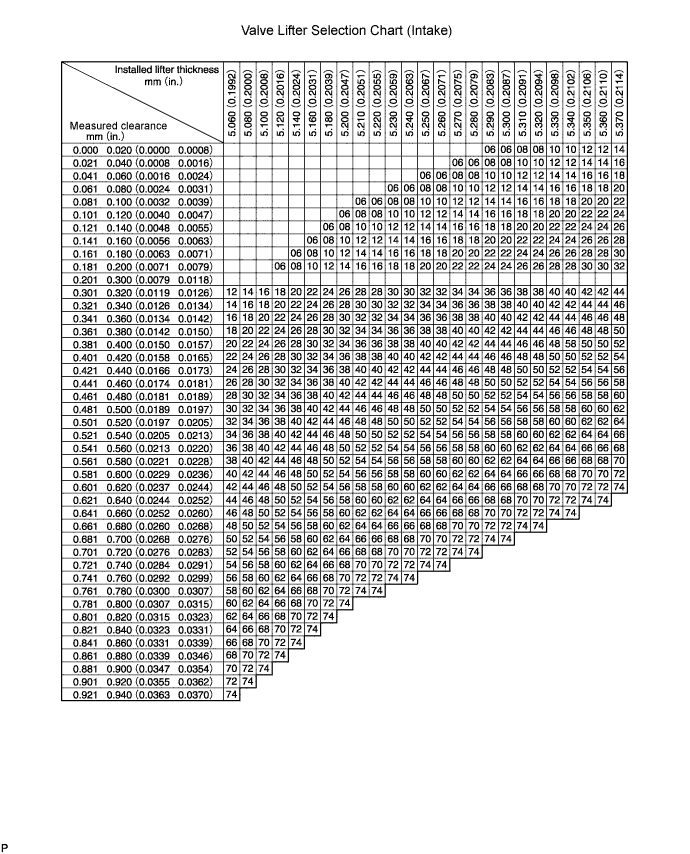
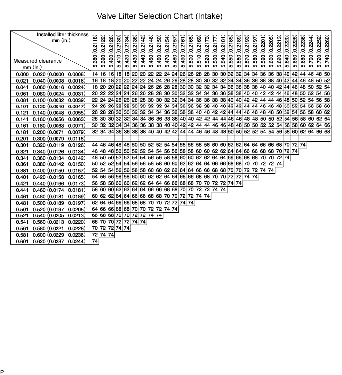
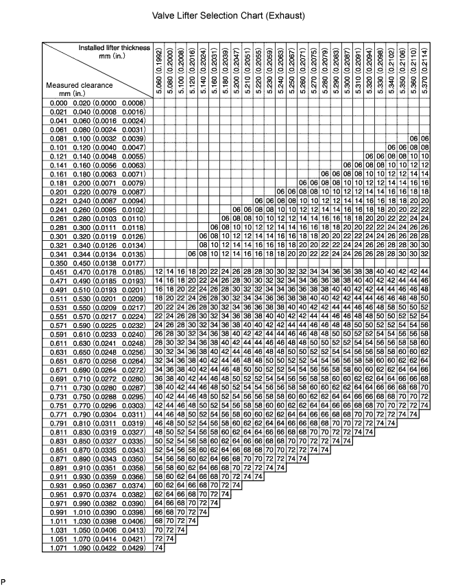
Calculate the thickness of a new lifter so that the valve clearance comes within the specified value.
| A | B | C |
| Thickness of new lifter | Thickness of used lifter | Measured valve clearance |
Select a new lifter with a thickness as close as possible to the calculated values.
Install the selected valve lifter.
| Shim No. | Thickness | Shim No. | Thickness | Shim No. | Thickness |
| 06 | 5.060 (0.1992) | 30 | 5.300 (0.2087) | 54 | 5.540 (0.2181) |
| 08 | 5.080 (0.2000) | 32 | 5.320 (0.2094) | 56 | 5.560 (0.2189) |
| 10 | 5.100 (0.2008) | 34 | 5.340 (0.2102) | 58 | 5.580 (0.2197) |
| 12 | 5.120 (0.2016) | 36 | 5.360 (0.2110) | 60 | 5.600 (0.2205) |
| 14 | 5.140 (0.2024) | 38 | 5.380 (0.2118) | 62 | 5.620 (0.2213) |
| 16 | 5.160 (0.2031) | 40 | 5.400 (0.2126) | 64 | 5.640 (0.2220) |
| 18 | 5.180 (0.2039) | 42 | 5.420 (0.2134) | 66 | 5.660 (0.2228) |
| 20 | 5.200 (0.2047) | 44 | 5.440 (0.2142) | 68 | 5.680 (0.2236) |
| 22 | 5.220 (0.2055) | 46 | 5.460 (0.2150) | 70 | 5.700 (0.2244) |
| 24 | 5.240 (0.2063) | 48 | 5.480 (0.2157) | 72 | 5.720 (0.2252) |
| 26 | 5.260 (0.2071) | 50 | 5.500 (0.2165) | 74 | 5.740 (0.2260) |
| 28 | 5.280 (0.2079) | 52 | 5.520 (0.2173) | - | - |
Install the camshaft.
Install the No. 2 timing belt cover.
Install the No. 1 timing belt idler.
Install the camshaft timing pulley.
Install the timing belt.
Install the No. 1 timing belt cover.
Install the fan shroud.
Add engine coolant.
| 11. INSTALL INJECTOR ASSEMBLY |
 |
Install 4 new injection nozzle sheets to the cylinder head.
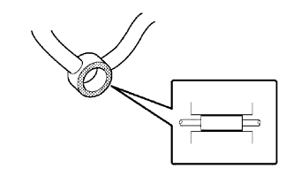
Apply a light amount of clean engine oil to 4 new O-rings.
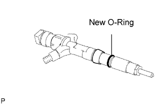 |
Install the O-ring to each injector as shown in the illustration.
Insert the 4 injectors into the cylinder head.
Register injector compensation code (when replacing with a new injector).
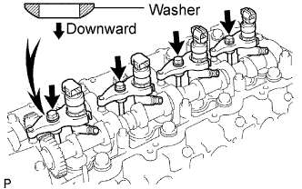 |
Temporarily install 4 new washers and the 4 nozzle clamps with the 4 clamp bolts.
Temporarily install the 4 injection pipes with the union nuts.
 |
Check the nozzle leakage pipe. Check that there are no scratches or dents on the 5 union seal surfaces.
If scratches or dents are present, replace the nozzle leakage pipe.
 |
Set the leakage pipe and 5 new gaskets in place.
Apply a light amount of oil to the 4 hollow screws and union bolt.
 |
Temporarily install the leakage pipe with the 4 hollow screws and union bolt.
Tighten the 4 holder clamp bolts.
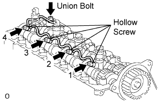 |
Tighten the 4 hollow screws in order from 1 to 4.
Tighten the union bolt.
Remove the 4 injection pipes.
| 12. CHECK FOR FUEL LEAKS |
 |
Check that there are no leaks from the nozzle leakage pipe connection.
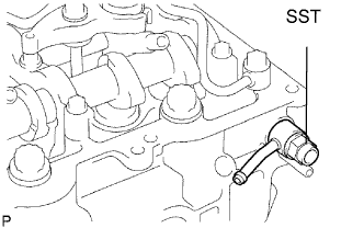
Install the gasket and No. 2 nozzle leakage pipe to the cylinder head with SST (check valve).
Apply a light amount of soapy water (or other fluid for detecting fuel leakage) on the nozzle leakage pipe connection.
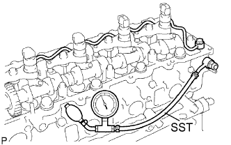 |
Install SST (turbocharger pressure gauge) to the fuel return side of the leakage pipe, and maintain 250 kPa (2.5 kgf/cm2, 35.5 psi) of pressure for 60 seconds to check that no bubbles form.
After checking for fuel leaks, wipe off the soapy water from the leakage pipe connection.
Remove SST, No. 2 nozzle leakage pipe and gasket.
| 13. INSTALL CYLINDER HEAD COVER SUB-ASSEMBLY |
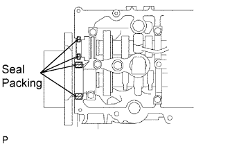 |
Remove any old seal packing (FIPG) material from the cylinder head.
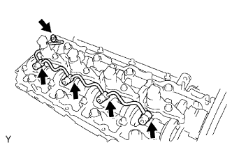
Apply seal packing to the specific areas shown in the illustration.
|
Install the gasket and cylinder head cover with the 10 bolts and 2 nuts.
Install 4 new nozzle holder seals.
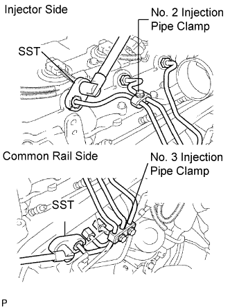
| 14. INSTALL INJECTION PIPE |
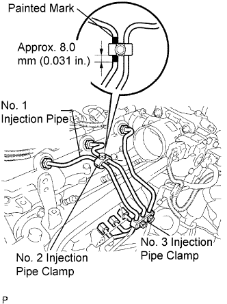 |
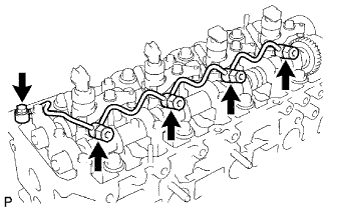
Temporarily install the No. 1, No. 2 and No. 3 injection pipes with the union nuts.
Install the No. 2 and No. 3 injection pipe clamps with the bolt and 2 nuts, as shown in the illustration.
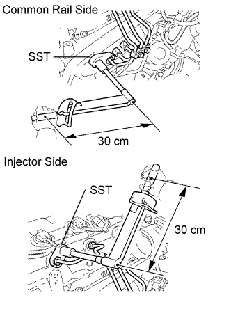 |
Using SST, tighten the injection pipe union nuts on the common rail side.
Using SST, tighten the injection pipe union nuts on the injector side.
|
Temporarily install the No. 4 injection pipe with the union nuts.
Install 2 new injection pipe clamps with the 2 bolts.
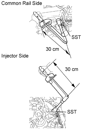 |
Using SST, tighten the injection pipe union nuts on the common rail side.
Using SST, tighten the injection pipe union nuts on the injector side.
| 15. INSTALL CHARGE AIR COOLER ASSEMBLY WITH INTAKE AIR CONNECTOR |
|
Install a new gasket and the intake air connector with the 4 bolts.
|
Using a 22 mm deep socket wrench, install a new gasket and the IAT sensor.
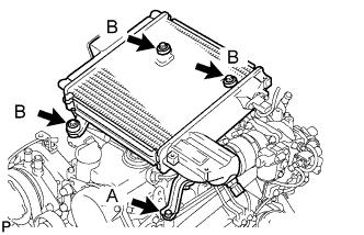 |
Install the CAC with the 4 bolts.
Tighten the 4 hose clamps of the No. 1 and No. 2 air hose.
Connect the diesel turbo IAT sensor connector.
| 16. INSTALL NO. 1 ENGINE COVER SUB-ASSEMBLY |
|
Install the cover with the 3 bolts and 2 nuts.
| 17. ADD FUEL |
| 18. TIGHTEN FUEL TANK CAP ASSEMBLY |
| 19. BLEED AIR FROM FUEL SYSTEM |
 |
Using the hand pump, bleed air from the fuel system until pumping becomes difficult.
| 20. CONNECT CABLE TO NEGATIVE BATTERY TERMINAL |
| 21. PERFORM INITIALIZATION |
Perform initialization (Click here).
| 22. CHECK FOR FUEL LEAKS |
| 23. CHECK FOR ENGINE OIL LEAKS |
