TURBOCHARGER > INSTALLATION |
| 1. CLEAN TURBOCHARGER SUB-ASSEMBLY |
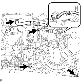
| 2. INSTALL TURBOCHARGER SUB-ASSEMBLY |
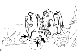 |
Temporarily install a new gasket and the turbocharger with 3 new nuts.
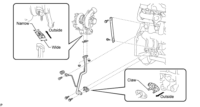
Temporarily install the turbo oil pipe and manifold stay.
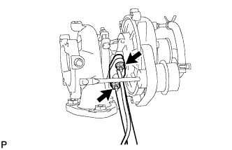 |
Temporarily install a new gasket and the oil pipe with the 2 nuts, but only loosely install the nuts.
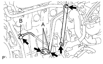 |
Temporarily install a new gasket and the oil pipe with the 2 bolts (labeled: A), but only loosely install the bolts.
Temporarily install a new gasket and the oil pipe with the union bolt (labeled: B), but only loosely install the union bolt.
Temporarily install the stay with the 2 bolts.
Tighten the bolts and nuts.
Tighten the 3 nuts of the turbocharger.
Tighten the 2 nuts of the oil pipe.
Tighten the 2 bolts of the oil pipe.
Tighten the union bolt.
Tighten the 2 bolts of the stay.
| 3. INSTALL TURBINE OUTLET ELBOW |
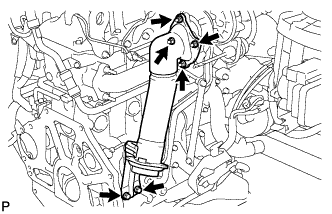 |
Temporarily install a new gasket and the outlet elbow (with turbocharger stay) to the turbocharger with the 4 nuts.
Temporarily install the stay with the 2 bolts.
Tighten the 4 nuts of the turbocharger.
Tighten the 2 bolts of the stay.
| 4. INSTALL AIR CLEANER PIPE SUB-ASSEMBLY |
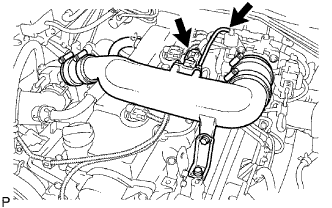 |
Connect the pipe (with the 2 air hoses) and install the bolt.
Tighten the 2 clamps of the No. 1 and No. 2 air hoses.
Connect the vacuum hose to the gas filter.
Connect the manifold absolute pressure sensor connector.
| 5. INSTALL VENTILATION HOSE HEAT INSULATOR |
Install the insulator with the 2 bolts.
| 6. INSTALL AIR CLEANER ASSEMBLY |
 |
Connect the air cleaner hose.
Install the air cleaner with the 2 bolts.
Tighten the clamp.
Install the clamp and connect the IAT connector.
Connect the ventilation hose.
Slide the clamp to the connection of the hose.
| 7. INSTALL FRONT EXHAUST PIPE ASSEMBLY |
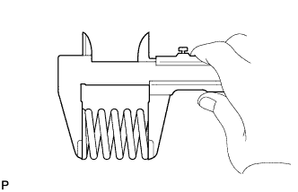 |
Using a vernier caliper, measure the free length of the compression spring.
Install the front pipe to the pipe support.
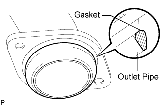 |
Install a new gasket to the outlet pipe.
Install the front pipe with the 2 compression springs and 2 bolts. Alternately tighten the bolts in several passes.
| 8. CONNECT CABLE TO NEGATIVE BATTERY TERMINAL |
| 9. CHECK FOR ENGINE OIL LEAKS |
| 10. CHECK FOR EXHAUST LEAKS |
| 11. INSTALL FRONT FENDER APRON SEAL UPPER |
Install the apron seal with the 5 clips.
| 12. INSTALL FRONT FENDER SEAL |
Install the fender seal with the 5 clips.
| 13. INSTALL FRONT WHEEL RH |
| 14. INSTALL NO. 1 ENGINE UNDER COVER |
Install the cover with the 4 bolts.
| 15. PERFORM INITIALIZATION |
Perform initialization (Click here).
