INTAKE MANIFOLD > INSTALLATION |
| 1. INSTALL INTAKE MANIFOLD |
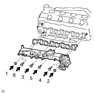 |
Temporarily install a new gasket and the manifold with the 2 nuts and 4 bolts.
Tighten the 2 nuts and 4 bolts in the order shown in the illustration.
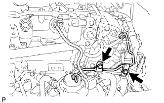
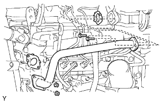
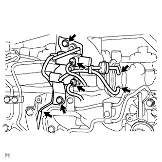
| 2. INSTALL NO. 2 NOZZLE LEAKAGE PIPE ASSEMBLY |
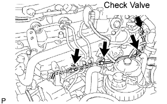 |
Temporarily install the leakage pipe with the 3 bolts.
Temporarily install a new gasket with the check valve.
Fully tighten the 3 bolts and check valve.
Connect the 2 fuel hoses.
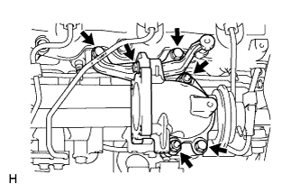
| 3. INSTALL INJECTION PIPE |
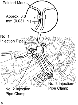 |
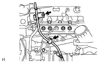
Temporarily install the No. 1, No. 2 and No. 3 injection pipes with the union nuts.
Install the No. 2 and No. 3 injection pipe clamps with the bolt and 2 nuts, as shown in the illustration.
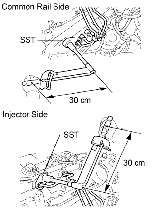 |
Using SST, tighten the injection pipe union nuts on the common rail side.
Using SST, tighten the injection pipe union nuts on the injector side.
 |
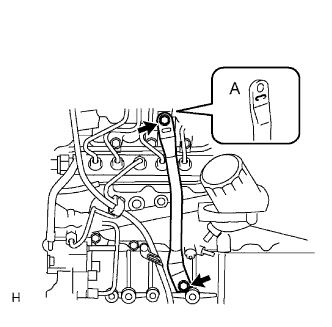
Temporarily install the No. 4 injection pipe with the union nuts.
Install 2 new injection pipe clamps with the 2 bolts.
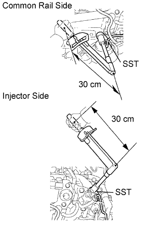 |
Using SST, tighten the injection pipe union nuts on the common rail side.
Using SST, tighten the injection pipe union nuts on the injector side.
| 4. INSTALL OIL LEVEL GAUGE GUIDE |
 |
Install a new O-ring to the guide.
Apply a small amount of clean engine oil to the O-ring.
Install the guide with the bolt.
Install the injection pipe clamp with the bolt.
| 5. INSTALL MANIFOLD STAY |
 |
Install the stay with the 2 bolts.
| 6. INSTALL EGR VALVE ASSEMBLY |
Install a new gasket and the EGR valve.
| 7. INSTALL NO. 1 EGR PIPE SUB-ASSEMBLY |
 |
Install 2 new gaskets and the pipe with the 2 nuts and 2 bolts.
| 8. INSTALL INTAKE AIR CONNECTOR |
 |
Install a new gasket and the air connector with the 2 nuts and bolt.
| 9. INSTALL THROTTLE BODY BRACKET |
Install the bracket with the 3 bolts.
| 10. INSTALL DIESEL THROTTLE BODY ASSEMBLY |
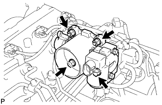 |
Install a new gasket and the throttle body with the 2 bolts and 2 nuts.
 |
Connect the 2 connectors.
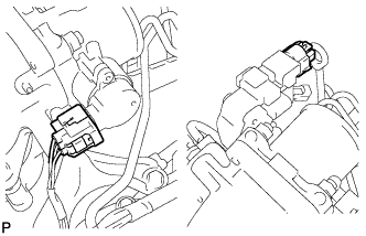
| 11. INSTALL VACUUM SWITCHING VALVE BRACKET |
 |
Install the bracket with the 2 bolts.
Connect the vacuum hoses to the 3 locations.
Connect the 2 connectors.
| 12. INSTALL CHARGE AIR COOLER ASSEMBLY WITH INTAKE AIR CONNECTOR |
Install the charge air cooler with intake air connector (Click here).
| 13. BLEED AIR FROM FUEL SYSTEM |
| 14. CONNECT CABLE TO NEGATIVE BATTERY TERMINAL |
| 15. CHECK FOR FUEL LEAKS |
 |
Check that there are no leaks from any part of the fuel system when the engine is stopped.
If there is fuel leakage, repair or replace parts as necessary.
Start the engine and check that there are no leaks from any part of the fuel system.
If there is fuel leakage, repair or replace parts as necessary.
Disconnect the return hose from the common rail.
Start the engine and check for fuel leaks from the return pipe.
If there is fuel leakage, replace the common rail.
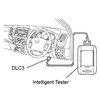
Connect the intelligent tester to the DLC3.
Start the engine and push the intelligent tester main switch ON.
Select the Fuel Leak test from the Active Test mode on the intelligent tester.
If the intelligent tester is not available, fully depress the accelerator pedal quickly. Increase the engine speed to the maximum and maintain that speed for 2 seconds. Repeat this operation several times.
Check that there are no leaks from any part of the fuel system.
Reconnect the return hose to the common rail.
| 16. INSTALL NO. 1 ENGINE COVER SUB-ASSEMBLY |
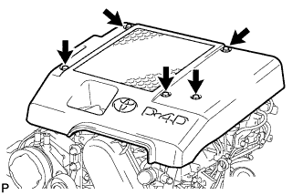 |
Install the cover with the 3 bolts and 2 nuts.
| 17. PERFORM INITIALIZATION |
Perform initialization (Click here).
