TURBOCHARGER > INSTALLATION |
| 1. CLEAN TURBOCHARGER SUB-ASSEMBLY |
| 2. INSTALL TURBOCHARGER SUB-ASSEMBLY |
 |
Temporarily install a new gasket and the turbocharger with 3 new nuts.
Temporarily install the turbo oil pipe.
Install a new gasket and the oil pipe with the 2 nuts, but only loosely install the nuts.
Install a new gasket and the oil pipe with the 2 bolts, but only loosely install the bolts.
Install a new gasket and the oil pipe with the union bolt, but only loosely install the union bolt.
 |
Temporarily install the turbocharger stay with the 3 bolts.
Tighten the 3 nuts of the turbocharger.
Tighten the 2 nuts and 2 bolts of the oil pipe, and the union bolt.
Tighten the 3 bolts of the turbocharger stay.
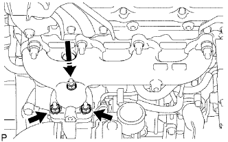
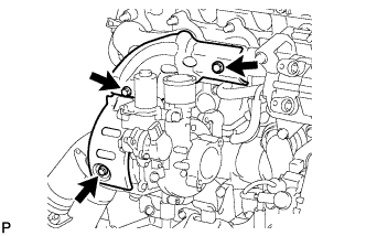
| 3. INSTALL TURBINE OUTLET ELBOW |
 |
Install a new gasket and the outlet elbow with the 3 nuts.
| 4. INSTALL NO. 1 TURBO WATER HOSE |
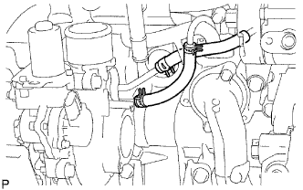 |
Connect the 2 hoses to the 2 tubes.
Move the 2 clamps to the locations where the hoses and tubes are connected.
| 5. INSTALL NO. 1 TURBO INSULATOR |
 |
Temporarily install the turbo insulator with the bolt.
| 6. INSTALL NO. 1 EXHAUST MANIFOLD HEAT INSULATOR |
Temporarily install the heat insulator with the 2 bolts.
Tighten the bolt of the turbo insulator, and the 2 bolts of the heat insulator.
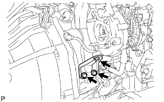
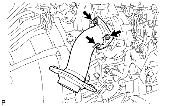
| 7. INSTALL COMPRESSOR INLET ELBOW |
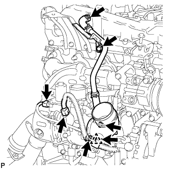 |
Install a new gasket and inlet elbow with the 2 nuts.
Connect the ventilation pipe to the cylinder head cover.
Move the clamp to the joint pipe of the hose.
Install the ventilation pipe with the bolt.
Connect the 2 connectors to the turbocharger.
Install the harness clamp's clip to the inlet elbow.
| 8. INSTALL CHARGE AIR COOLER WITH INTAKE AIR CONNECTOR |
Install the charge air cooler with intake air connector (Click here).
| 9. INSTALL NO. 1 ENGINE COVER SUB-ASSEMBLY |
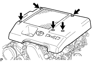 |
Install the cover with the 3 bolts and 2 nuts.
| 10. INSTALL AIR CLEANER ASSEMBLY |
 |
Connect the air cleaner hose.
Install the cleaner with the 2 bolts.
Tighten the hose clamp of the compressor inlet elbow.
Connect the MAF meter connector and install the clamp.
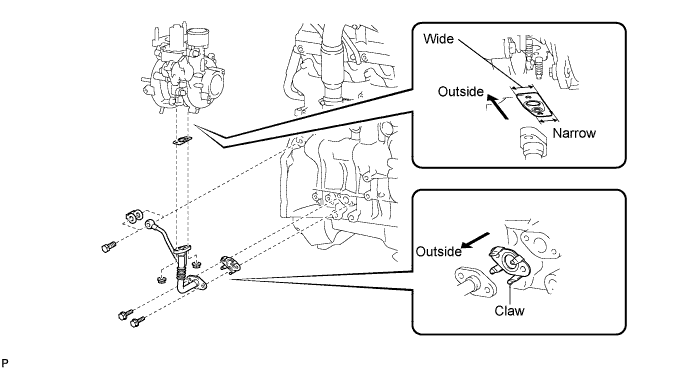
| 11. INSTALL FRONT EXHAUST PIPE ASSEMBLY |
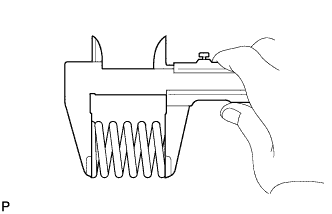 |
Using a vernier caliper, measure the free length of the compression spring.
Install the front pipe to the pipe support.
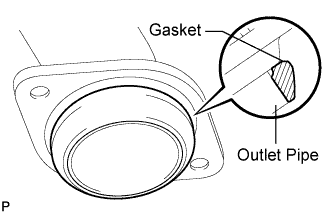 |
Install a new gasket to the outlet pipe.
Install the front pipe with the 2 compression springs and 2 bolts. Alternately tighten the bolts in several passes.
| 12. INSTALL FRONT FENDER APRON SEAL UPPER |
Install the apron seal with the 5 clips.
| 13. INSTALL FRONT FENDER SEAL |
Install the seal with the 5 clips.
| 14. INSTALL FRONT WHEEL RH |
| 15. CONNECT CABLE TO NEGATIVE BATTERY TERMINAL |
| 16. ADD ENGINE COOLANT |
Tighten the radiator drain cock plug by hand.
Tighten the cylinder block drain cock plug.
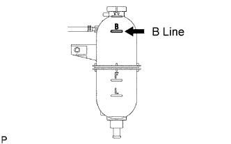 |
Fill the radiator with TOYOTA Super Long Life Coolant (SLLC) to the reservoir tank's B line.
| Item | Specified Condition |
| A/T | 11.1 liters (11.7 US qts, 9.8 lmp. qts) |
| M/T | 9.8 liters (10.4 US qts, 8.6 lmp. qts) |
Press the inlet and outlet radiator hoses several times by hand, and then check the level of the coolant.
If the coolant level drops below the B line, add TOYOTA SLLC to the B line.
Install the radiator reservoir cap.
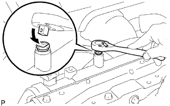 |
Using a wrench, install the vent plug.
Bleed air from the cooling system.
Warm up the engine until the thermostat opens. While the thermostat is open, circulate the coolant for several minutes.
Maintain the engine speed at 2,000 to 2,500 rpm.
Press the inlet and outlet radiator hoses several times by hand to bleed air.
Stop the engine and wait until the coolant cools down to ambient temperature.
 |
After the coolant cools down, check that the coolant level is at the F line.
If the coolant level is below the F line, add TOYOTA SLLC to the F line.
| 17. CHECK FOR ENGINE COOLANT LEAKS |
Check for the engine coolant leaks (Click here).
| 18. CHECK FOR ENGINE OIL LEAKS |
| 19. PERFORM INITIALIZATION |
Perform initialization (Click here).
