EMISSION CONTROL SYSTEM (for Unleaded Gasoline Specification Vehicle) > SYSTEM DIAGRAM

for Preparation Click here


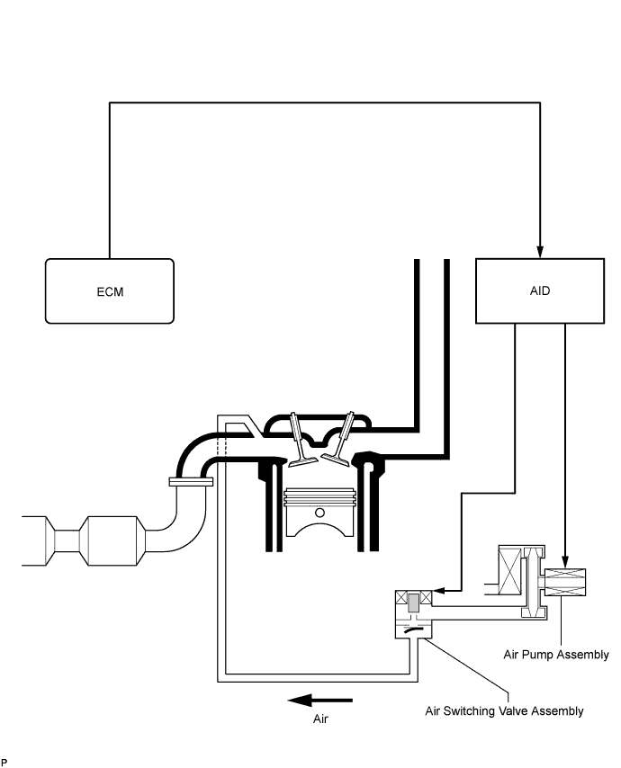
SECONDARY AIR INJECTION SYSTEM ILLUSTRATION
During a cold engine start, this system purifies the catalyst exhaust fumes by applying air pressure to the air hose, exhaust manifold and cylinder head exhaust port.

A110274E02


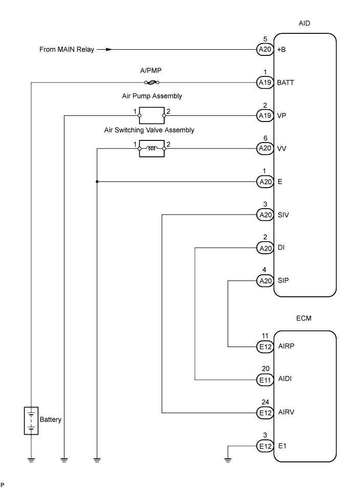
SECONDARY AIR INJECTION SYSTEM WIRING DIAGRAM

A110275E02


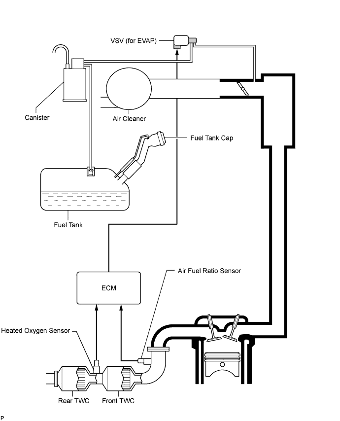
EMISSION CONTROL AND EVAP CONTROL SYSTEM ILLUSTRATION
To reduce HC emissions, the following occurs. First, evaporated fuel in the fuel tank is absorbed by the canister's active carbon. Then, when the vehicle is being driven, the fuel in the canister and air are routed into the intake manifold for combustion.

A110269E01


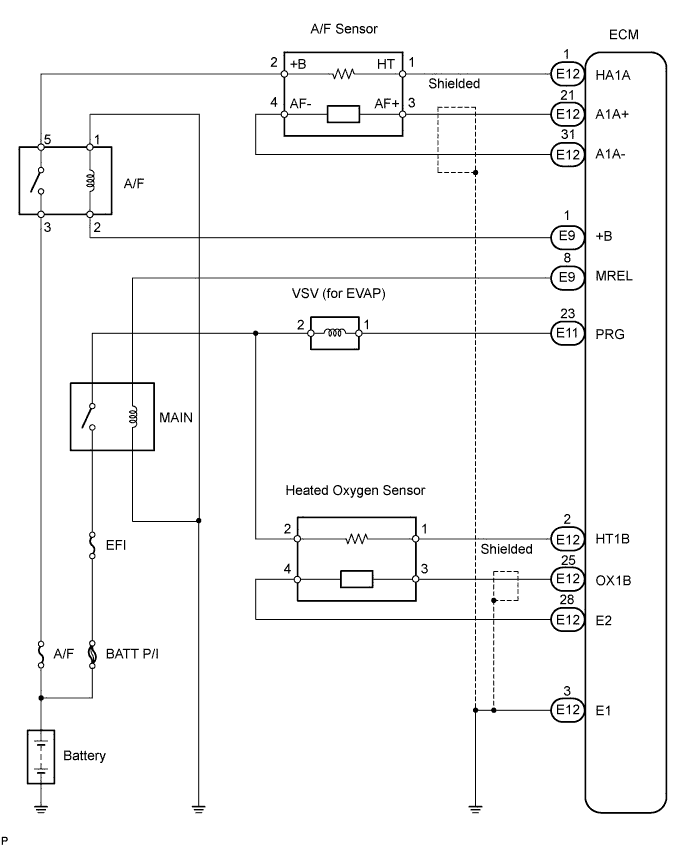
EMISSION CONTROL AND EVAP CONTROL WIRING DIAGRAM

A110270E01