EMISSION CONTROL SYSTEM > ON-VEHICLE INSPECTION |
| 1. INSTALL VACUUM GAUGE |
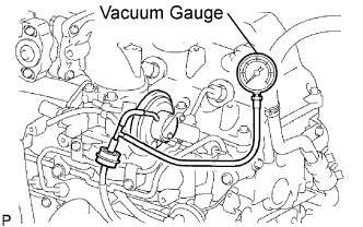 |
Using a 3-way connector, connect a vacuum gauge to the hose between the EGR valve and E-VRV.
| 2. CHECK SEATING OF EGR VALVE |
Start the engine. Check that the engine starts and then idles.
| 3. CHECK OUTPUT VACUUM WITH VACUUM GAUGE |
Connect a vacuum gauge to the output pipe.
Warm up the engine and check that the vacuum gauge reading is above 28.0 kPa (210 mmHg, 8.3 in.Hg).
If the result is not as specified, check for leaks between the EGR valve and vacuum pump, or check the EGR valve.
| 4. CHECK HOT ENGINE CONDITION |
Visually check the vacuum hose between the vacuum pump and EGR valve for leaks.
Warm up the engine.
The coolant temperature should be above 75°C (109°F) and below 90°C (194°F).
Check that the vacuum gauge reading is more than 28.0 kPa (210 mmHg, 8.3 in.Hg) at idle.
Check that the vacuum gauge indicator reading increases by more than 28.0 kPa (210 mmHg, 8.3 in.Hg) at 1,500 rpm.
When the accelerator pedal is fully depressed quickly, check that the vacuum gauge indicator drops momentarily.
Keep the engine speed at more than 4,000 rpm.
Check that the vacuum gauge reading is as shown below.
When the accelerator pedal is released, check that the vacuum gauge indicator drops momentarily while the engine speed decreases from more than 4,000 rpm to idle.
If the result is not as specified, refer to the INSPECTION section (Click here).
| 5. REMOVE VACUUM GAUGE |
| 6. VISUALLY CHECK HOSES, CONNECTIONS AND GASKETS |
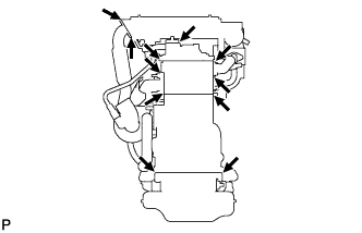 |
Check that there are no cracks, leaks or damage.
| 7. CHECK VACUUM PUMP ASSEMBLY |
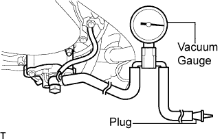 |
Disconnect the vacuum hose from the vacuum pump.
Connect the hose of a vacuum gauge to the pump.
Insert a plug into the other hose of the gauge.
Start the engine and warm it up for more than 2 minutes.
With the engine idling, check the negative pressure of the pump.
Remove the gauge from the pump.
Connect the hose to the pump with the clip.
