DTC No.
| DTC Detection Condition
| Trouble Area
|
P0710/38
| - ATF temperature sensor resistance changes from (a) to (b) or from (b) to (a) in less than 0.5 sec., and P0712/38 and P0713/38 are not detected (1 trip detection logic):
- ATF temperature sensor resistance is less than 79 Ω
- ATF temperature sensor resistance is more than 156 kΩ
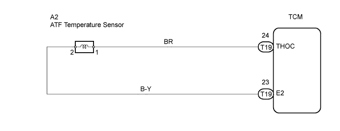
| - Open or short in ATF temperature sensor circuit
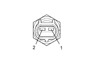
- ATF temperature sensor
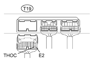
- TCM
|
P0712/38
| ATF temperature sensor resistance is less than 79 Ω for 0.5 sec. or more (1 trip detection logic)
| - Short in ATF temperature sensor circuit
- ATF temperature sensor
- TCM
|
P0713/38
| - ATF temperature sensor resistance is more than 156 kΩ for 15 minutes or more after the engine starts
- DTC is detected for 0.5 sec. or more (1 trip detection logic)
| - Open in ATF temperature sensor circuit
- ATF temperature sensor
- TCM
|