DTC P0973/62 Shift Solenoid "A" Control Circuit Low (Shift Solenoid Valve S1) |
DTC P0974/62 Shift Solenoid "A" Control Circuit High (Shift Solenoid Valve S1) |
DTC P0976/63 Shift Solenoid "B" Control Circuit Low (Shift Solenoid Valve S2) |
DTC P0977/63 Shift Solenoid "B" Control Circuit High (Shift Solenoid Valve S2) |
| Position | Normal | Shift Solenoid S1 Malfunctioning | Shift Solenoid S2 Malfunctioning | Both Solenoids Malfunctioning | ||||||
| Solenoid valve | Gear | Solenoid valve | Gear | Solenoid valve | Gear | Gear when shift selector is manually operated | ||||
| S1 | S2 | S1 | S2 | S1 | S2 | |||||
| D | ON | OFF | 1st | X | ON | 3rd | ON | X | 1st | O/D |
| ON | ON | 2nd | X | ON | 3rd | OFF | X | O/D | O/D | |
| OFF | ON | 3rd | X | ON | 3rd | OFF | X | O/D | O/D | |
| OFF | OFF | O/D | X | OFF | O/D | OFF | X | O/D | O/D | |
| 2 | ON | OFF | 1st | X | ON | 3rd | ON | X | 1st | 3rd |
| ON | ON | 2nd | X | ON | 3rd | OFF | X | 3rd | 3rd | |
| OFF | ON | 3rd | X | ON | 3rd | OFF | X | 3rd | 3rd | |
| L | ON | OFF | 1st | X | OFF | 1st | ON | X | 1st | 1st |
| ON | ON | 2nd | X | ON | 2nd | ON | X | 1st | 1st | |
| DTC No. | DTC Detection Condition | Trouble Area |
| P0973/62 | TCM detects short in solenoid valve S1 circuit 4 times when solenoid valve S1 is operated (1 trip detection logic) |
|
| P0974/62 | TCM detects open in solenoid valve S1 circuit 4 times when solenoid valve S1 is not operated (1 trip detection logic) |
|
| P0976/63 | TCM detects short in solenoid valve S2 circuit 4 times when solenoid valve S2 is operated (1 trip detection logic) |
|
| P0977/63 | TCM detects open in solenoid valve S2 circuit 4 times when solenoid valve S2 is not operated (1 trip detection logic) |
|
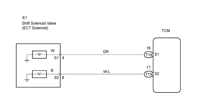
| 1.INSPECT TRANSMISSION WIRE (SHIFT SOLENOID VALVE S1/S2) |
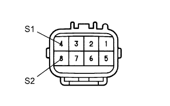 |
Disconnect the E1 wire connector.
Measure the resistance of the transmission wire.
| Tester Connection | Condition | Specified Condition |
| 4 (S1) - Body ground | 20°C (68°F) | 11 to 15 Ω |
| 8 (S2) - Body ground | 20°C (68°F) | 11 to 15 Ω |
|
| ||||
| OK | |
| 2.CHECK WIRE HARNESS (SHIFT SOLENOID VALVE S1/S2 - TCM) |
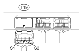 |
Disconnect the T19 TCM connector.
Measure the resistance of the wire harness side connector.
| Tester Connection | Condition | Specified Condition |
| T19-18 (S1) - Body ground | 20°C (68°F) | 11 to 15 Ω |
| T19-17 (S1) - Body ground | 20°C (68°F) | 11 to 15 Ω |
|
| ||||
| OK | ||
| ||
| 3.INSPECT SHIFT SOLENOID VALVE S1/S2 |
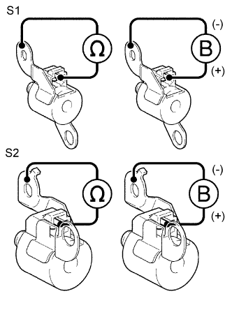 |
Remove the shift solenoid valve S1/S2.
Measure the resistance between the solenoid valve terminal and solenoid valve body.
Connect the battery's positive (+) lead to the terminal of the solenoid connector, and the negative (-) lead to the solenoid body.
|
| ||||
| OK | ||
| ||
