DTC P0722/61 Output Speed Sensor Circuit No Signal |
| DTC No. | DTC Detection Condition | Trouble Area |
| P0722/61 |
|
|
| 1.CHECK NO. 2 VEHICLE SPEED SENSOR INSTALLATION |
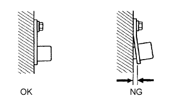 |
Check the speed sensor installation.
|
| ||||
| OK | |
| 2.INSPECT NO. 2 VEHICLE SPEED SENSOR |
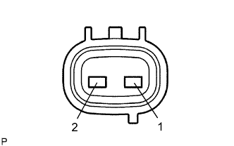 |
Disconnect the T7 sensor connector from the transmission.
Measure the resistance of the sensor.
| Tester Connection | Condition | Specified Condition |
| 1 - 2 | 20°C (68°F) | 560 to 680 Ω |
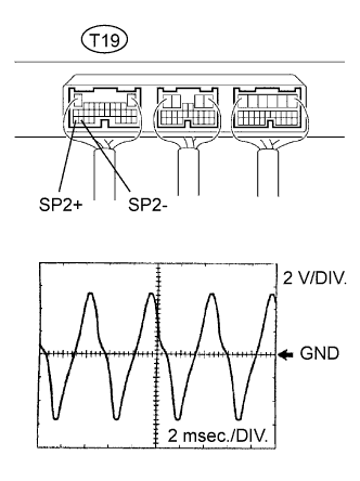 |
| Item | Content |
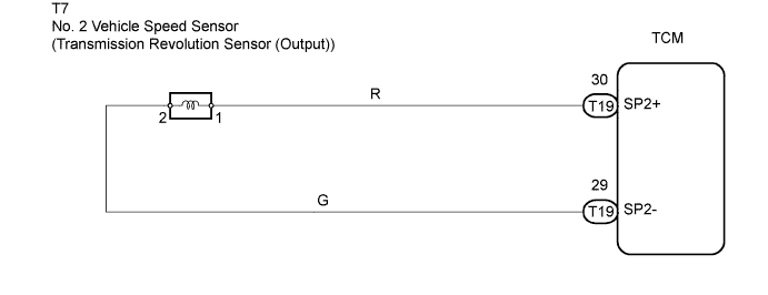
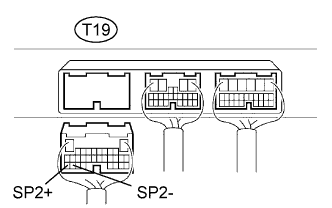
| Test Connection | T19-30 (SP2+) - T19-29 (SP2-) |
| Tool Setting | 2 V/DIV., 2 msec./DIV. |
| Condition | Vehicle speed 20 km/h (12 mph) |
|
| ||||
| OK | |
| 3.CHECK WIRE HARNESS (NO. 2 VEHICLE SPEED SENSOR - TCM) |
 |
Disconnect the T19 TCM connector.
Measure the resistance of the wire harness side connector.
| Tester Connection | Condition | Specified Condition |
| T19-30 (SP2+) - T19-29 (SP2-) | 20°C (68°F) | 560 to 680 Ω |
| T19-30 (SP2+) - Body ground | 20°C (68°F) | 10 kΩ or higher |
| T19-29 (SP2-) - Body ground | 20°C (68°F) | 10 kΩ or higher |
|
| ||||
| OK | ||
| ||
