ELECTRONIC CONTROLLED AUTOMATIC TRANSMISSION SYSTEM > Stop Light Switch Circuit

for Preparation Click here


DESCRIPTION

The purpose of this circuit is to prevent the engine from stalling while driving in the lock-up condition and the brakes are suddenly applied.
When the brake pedal is depressed, this switch sends a signal to the TCM. Then the TCM cancels the operation of the lock-up clutch during braking.

WIRING DIAGRAM


G034504E03


INSPECTION PROCEDURE

HINT:
Using the intelligent tester's Data List allows switch, sensor, actuator and other item values to be read without removing any parts. Reading the Data List early in troubleshooting is one way to save time.

  1. Warm up the engine.
  2. Turn the ignition switch OFF.
  3. Connect the intelligent tester to the DLC3.
  4. Turn the ignition switch ON and push the tester main switch ON.
  5. Enter the following menus: Powertrain / ECT / Data List.
  6. Follow the instructions on the tester and read the Data List.

Item
Measurement Item/
Range (Display)
Normal Condition
Diagnostic Note
Stop Light Switch
Stop light switch status/
ON or OFF
  1. Brake pedal is depressed: ON
  2. Brake pedal is released: OFF
-

NOTICE:
In the table above, the values listed under "Normal Condition" are reference values. Do not depend solely on these reference values when deciding whether a part is faulty or not.

1.INSPECT STOP LIGHT SWITCH


    E065594E03
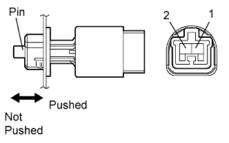
  1. Remove the stop light switch.

  1. Measure the resistance of the switch.

    Standard resistance:
    Tester Connection
    Switch Condition
    Specified Condition
    1 - 2
    Pin pushed
    (pedal released)
    10 kΩ or higher
    1 - 2
    Pin not pushed
    (pedal depressed)
    Below 1 Ω


NG
REPLACE STOP LIGHT SWITCH
OK


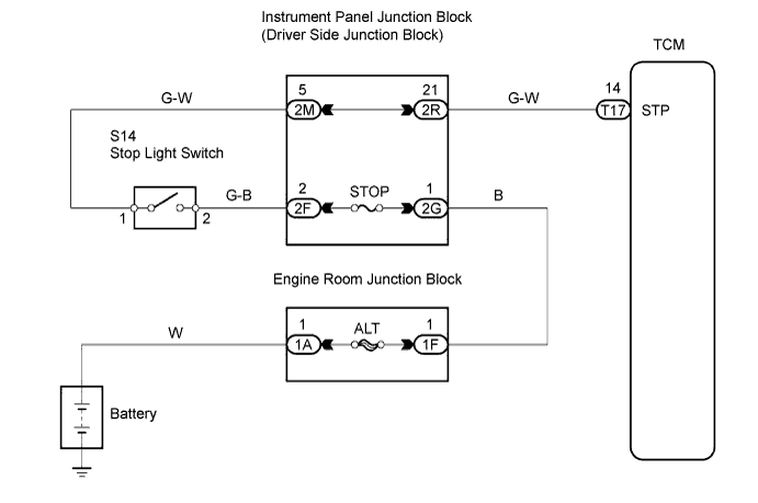
2.CHECK WIRE HARNESS (TCM - BATTERY)


    G039243E03
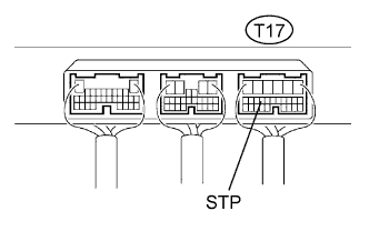
  1. Measure the voltage of the wire harness side connector.

    Standard voltage:
    Tester Connection
    Condition
    Specified Condition
    T17-14 (STP) - Body ground
    Brake pedal is depressed
    10 to 14 V
    T17-14 (STP) - Body ground
    Brake pedal is released
    Below 1 V


NG
REPAIR OR REPLACE HARNESS AND CONNECTOR
OK

PROCEED TO NEXT CIRCUIT INSPECTION SHOWN IN PROBLEM SYMPTOMS TABLE