DTC P0500/42 Vehicle Speed Sensor Malfunction |
| DTC No. | DTC Detection Condition | Trouble Area |
| P0500/42 |
|
|
| 1.READ DATA LIST (VEHICLE SPEED) |
Connect the intelligent tester to the DLC3.
Start the engine and turn the intelligent tester ON.
Enter the following menus: Powertrain / ECT / Data List / Vehicle SPD.
Check the vehicle speed at an engine speed of 2,000 rpm or more while the vehicle is running.
|
| ||||
| NO | |
| 2.CHECK OPERATION OF SPEEDOMETER |
Check the speedometer reading in the combination meter.
|
| ||||
| OK | |
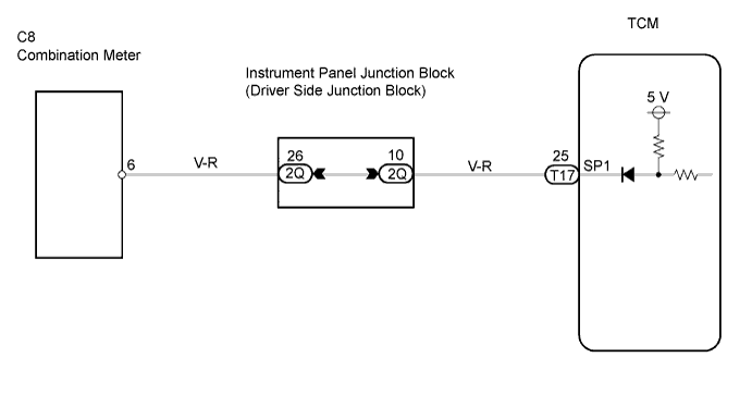
| 3.CHECK TCM (SP1 SIGNAL) |
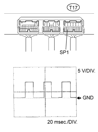 |
While idling, check the waveform of the TCM connectors using an oscilloscope.
Move the shift lever to N.
Jack up one of the rear wheels.
Turn the ignition switch ON.
Measure the voltage of the TCM connectors as the wheel is turned slowly.
| Item | Content |
| Tester Connection | T17-25 (SP1) - Body ground |
| Tool Setting | 5 V/DIV., 20 msec./DIV. |
| Condition | Turn the rear wheel slowly |
|
| ||||
| OK | ||
| ||
| 1.CHECK OPERATION OF SPEEDOMETER |
Check the speedometer reading in the combination meter.
|
| ||||
| OK | |
| 2.CHECK TCM |
|
While idling, check the waveform of the TCM connectors using an oscilloscope.
Move the shift lever to N.
Jack up one of the rear wheels.
Turn the ignition switch ON.
Measure the voltage of the TCM connectors as the wheel is turned slowly.
| Item | Content |
| Tester Connection | T17-25 (SP1) - Body ground |
| Tool Setting | 5 V/DIV., 20 msec./DIV. |
| Condition | Turn the rear wheel slowly |
|
| ||||
| OK | ||
| ||
