AUTOMATIC TRANSMISSION UNIT > DISASSEMBLY |
| 1. REMOVE TRANSMISSION CONTROL SHAFT LEVER LH |
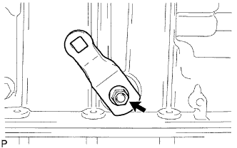 |
Remove the nut, washer and control shaft lever LH.
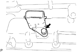
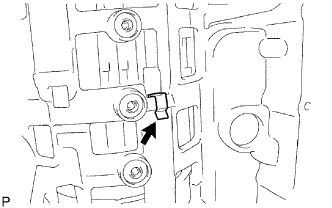
| 2. REMOVE PARK/NEUTRAL POSITION SWITCH ASSEMBLY |
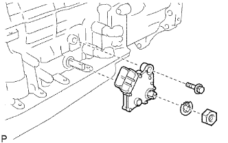 |
Using a screwdriver, pry out the lock washer.
Remove the nut, lock washer and bolt.
Remove the park/neutral position switch.
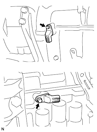
| 3. REMOVE OIL COOLER TUBE UNION |
Remove the 2 oil cooler tube unions.
Remove the O-ring from the oil cooler tube union.
| 4. REMOVE SPEED SENSOR |
 |
Remove the 2 bolts and 2 transmission revolution sensors.
Remove the O-ring from each sensor.
| 5. REMOVE AUTOMATIC TRANSAXLE BREATHER TUBE |
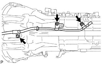 |
Remove the 3 bolts.
Remove the breather tube.
Remove the O-ring from each tube.
| 6. REMOVE AUTOMATIC TRANSMISSION HOUSING |
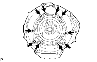 |
Remove the 10 bolts.
Remove the transmission housing.
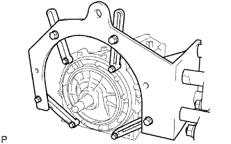
| 7. REMOVE EXTENSION HOUSING SUB-ASSEMBLY |
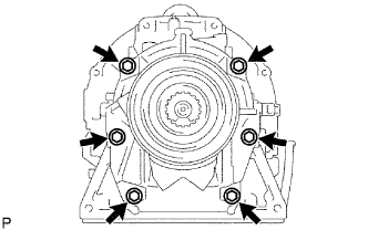 |
Remove the 6 bolts.
Remove the extension housing assembly.
Remove the gasket from the extension housing assembly.
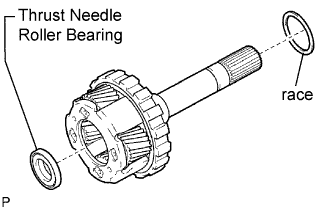
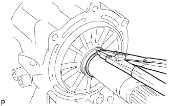 |
Using a snap ring expander, remove the snap ring.
Remove the thrust needle roller bearing and 2 bearing races.
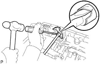
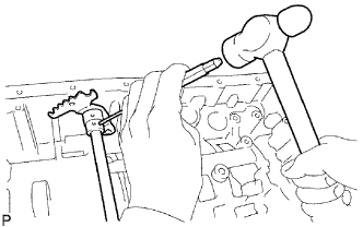
| 8. REMOVE EXTENSION HOUSING DUST DEFLECTOR |
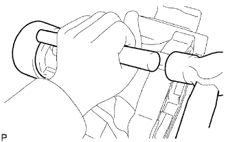 |
Using a brass bar and hammer, remove the extension housing dust deflector.
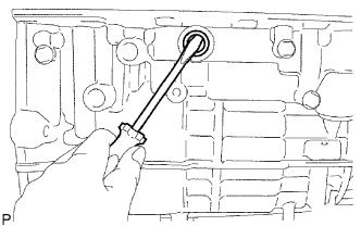
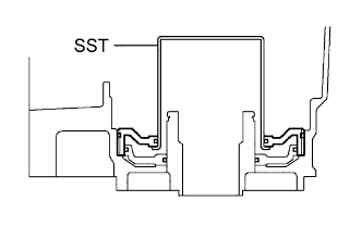
| 9. REMOVE AUTOMATIC TRANSMISSION EXTENSION HOUSING OIL SEAL |
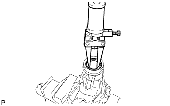 |
Using SST, tap out the oil seal.
| 10. FIX AUTOMATIC TRANSMISSION CASE SUB-ASSEMBLY |
 |
Install the transmission case on the overhaul attachment.
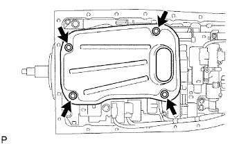
| 11. REMOVE AUTOMATIC TRANSMISSION OIL PAN SUB-ASSEMBLY |
Remove the drain plug and 20 bolts.
| 12. INSPECT AUTOMATIC TRANSMISSION OIL PAN SUB-ASSEMBLY |
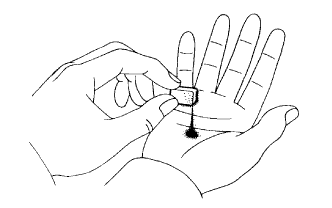 |
Remove the magnets, and use them to collect steel particles.
Carefully lock at the foreign matter and particles in the pan and on the magnets to anticipate the type of wear you will find in the transmission.
| 13. REMOVE VALVE BODY OIL STRAINER ASSEMBLY |
 |
Turn over the transmission.
Remove the 4 bolts holding the valve body oil strainer assembly to the valve body.
Remove the O-ring form the valve body oil strainer assembly.
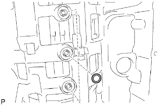
| 14. REMOVE TRANSMISSION WIRE |
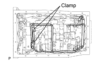 |
Remove the ATF temperature sensor.
Remove the bolt and clamp.
Disconnect the 7 connectors from the shift solenoid valves.
 |
Remove the bolt from the case.
Pull the transmission wire out of the transmission case.
Remove the O-ring from the transmission wire.
| 15. REMOVE TRANSMISSION VALVE BODY ASSEMBLY |
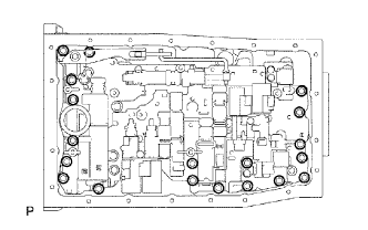 |
Remove the 19 bolts.
Remove the valve body assembly.
| 16. REMOVE TRANSAXLE CASE GASKET |
 |
Remove the 3 transaxle case gaskets.
| 17. REMOVE BRAKE DRUM GASKET |
 |
Remove the 3 brake drum gaskets.
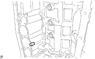
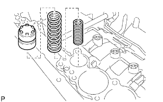
| 18. REMOVE CHECK BALL BODY |
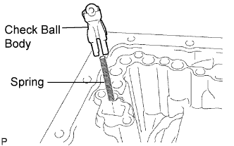 |
Remove the check ball body and spring.
| 19. REMOVE C-2 ACCUMULATOR PISTON |
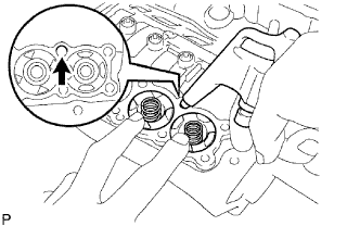 |
Applying compressed air to the oil hole, and remove the C2 accumulator piston and spring.
Remove the 2 O-rings from the piston.
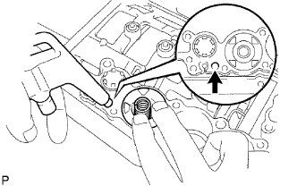
| 20. REMOVE B-3 ACCUMULATOR PISTON |
|
Applying compressed air to the oil hole, and remove the C2 accumulator piston and spring.
Remove the 2 O-rings from the piston.
| 21. REMOVE C-3 ACCUMULATOR PISTON |
 |
Applying compressed air to the oil hole, and remove the B-3 accumulator piston and spring.
Remove the 2 O-rings from the piston.
| 22. REMOVE C-1 ACCUMULATOR VALVE |
 |
Remove the C-1 accumulator valve and 2 springs.
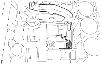
| 23. REMOVE PARKING LOCK PAWL BRACKET |
 |
Remove the 3 bolts and parking lock pawl bracket.
| 24. REMOVE PARKING LOCK ROD SUB-ASSEMBLY |
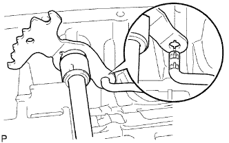 |
Disconnect the parking lock rod from the manual valve lever.
| 25. REMOVE PARKING LOCK PAWL SHAFT |
 |
Pull out the parking lock pawl shaft from the front side, and then remove the lock pawl and spring.
Remove the E-ring from the shaft.
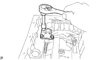
| 26. REMOVE MANUAL VALVE LEVER SUB-ASSEMBLY |
 |
Using a hammer and screwdriver, cut off the spacer and remove it from the shaft.
 |
Using a pin punch and hammer, tap out the spring pin.
Pull the manual valve lever shaft out through the case, and remove the manual valve lever.
| 27. REMOVE MANUAL VALVE LEVER SHAFT OIL SEAL |
 |
Using a screwdriver, remove the 2 oil seals.
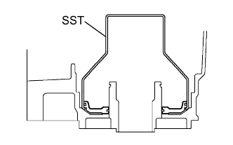
| 28. REMOVE OIL PUMP ASSEMBLY |
 |
Remove the 10 bolts holding the oil pump from the transmission case.
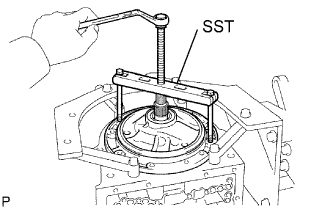 |
Using SST, remove the oil pump.
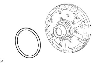 |
Remove the No. 1 thrust bearing race from the front oil pump.
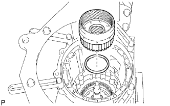
| 29. REMOVE CLUTCH DRUM AND INPUT SHAFT ASSEMBLY |
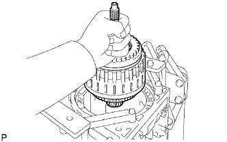 |
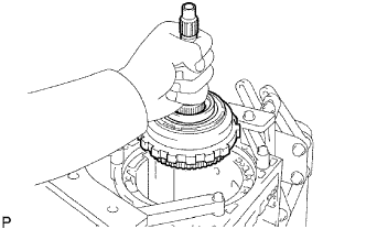
Remove the clutch drum and input shaft drum assembly from the transmission case.
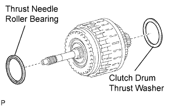 |
Remove the clutch drum thrust washer and thrust needle roller bearing.
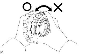
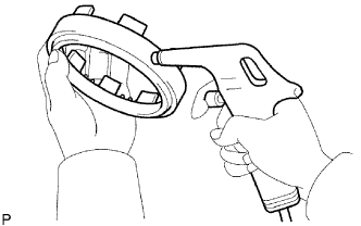
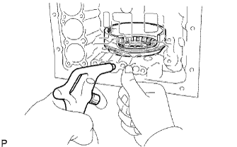
| 30. INSPECT 1-WAY NO. 2 CLUTCH ASSEMBLY |
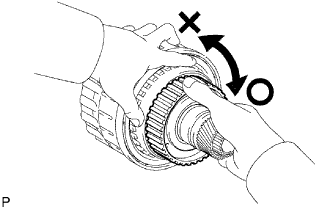 |
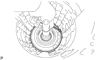
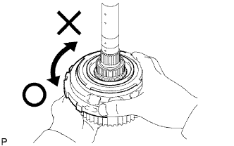
Hold the Reverse clutch hub and turn the No. 2 1-way clutch assembly
The No. 2 1-way clutch assembly turns freely clockwise and locks when turned counterclockwise.
| 31. REMOVE 1-WAY NO. 2 CLUTCH ASSEMBLY |
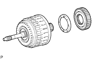 |
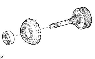
Remove the No. 2 1-way clutch assembly and No. 2 clutch drum thrust washer from the clutch drum and input shaft assembly.
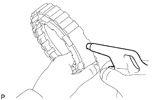
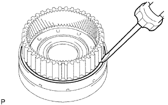
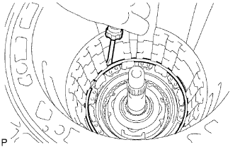
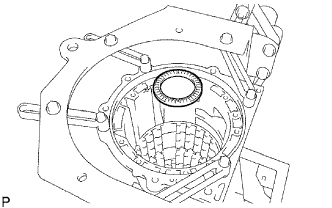
| 32. REMOVE NO. 3 BRAKE SNAP RING |
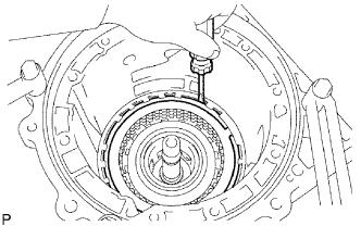 |
Using a screwdriver, remove the No. 3 brake snap ring from the case.
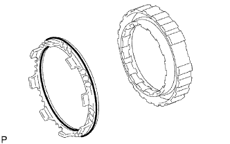
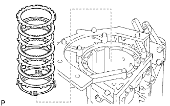
| 33. REMOVE NO. 3 BRAKE DISC |
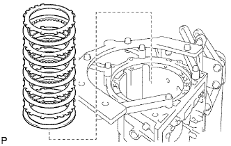 |
Remove the flange and cushion plate the 4 discs and the 4 plates from the case.
| 34. INSPECT NO. 3 BRAKE DISC |
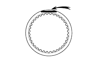 |
Replace all discs if one of the following problems is present: 1) a disc, plate or flange is worn or burnt, 2) the lining of a disc is peeled off or discolored, or 3) grooves or printed numbers have even a little bit of damage.
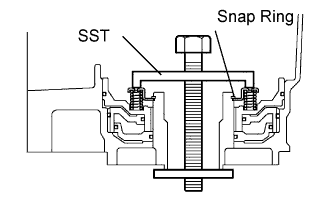
| 35. REMOVE 2ND BRAKE PISTON HOLE SNAP RING |
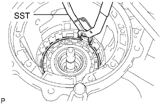 |
Using SST, remove the snap ring.
| 36. REMOVE 1-WAY CLUTCH ASSEMBLY |
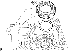 |
Remove the 1-way clutch assembly and the No. 1 planetary carrier thrust washer from the case.
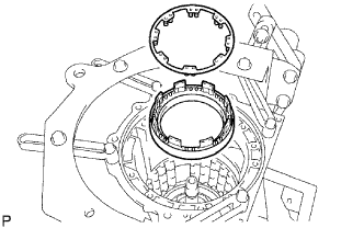
| 37. REMOVE 2ND BRAKE CYLINDER |
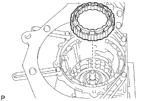 |
Remove the 2nd brake cylinder from the case.
| 38. REMOVE 2ND BRAKE PISTON |
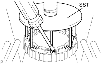 |
Using SST and a press, remove the snap ring.
 |
Hold the 2nd brake piston and apply compressed air (392 kPa, 4.0 kgf/cm2, 57 psi) to the brake cylinder to remove the 2nd brake piston.
 |
Remove the 2 O-rings from the 2nd brake piston.
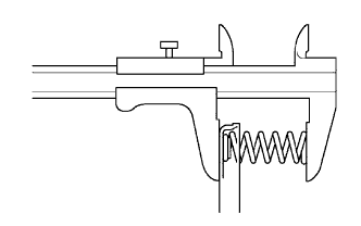
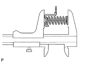
| 39. INSPECT NO. 3 BRAKE PISTON RETURN SPRING SUB-ASSEMBLY |
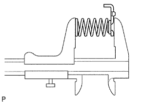 |
Using a vernier caliper, measure the free length of the spring together with the spring seat.
| 40. REMOVE FRONT PLANETARY GEAR ASSEMBLY |
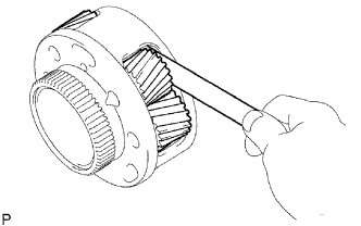 |
Using a feeler gauge, measure the front planetary pinion gear thrust clearance.
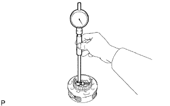 |
Using a dial indicator, measure the inside diameter of the front planetary gear bushing.
| 41. INSPECT FRONT PLANETARY GEAR ASSEMBLY |
|
Using a feeler gauge, measure the front planetary pinion gear thrust clearance.
|
Using a dial indicator, measure the inside diameter of the front planetary gear bushing.
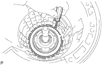
| 42. INSPECT 1-WAY CLUTCH ASSEMBLY |
 |
Install the 1-way clutch assembly to the 1-way clutch inner race.
Hold the 1-way clutch inner race and turn the 1-way clutch assembly.
Check that the 1-way clutch assembly turns freely counterclockwise and locks when turned clockwise.
Remove the 1-way clutch assembly from the 1-way clutch inner race.
| 43. REMOVE FRONT PLANETARY RING GEAR |
 |
Remove the front planetary ring gear and bearing from the transmission case.
| 44. REMOVE CENTER PLANETARY RING GEAR |
 |
Using a screwdriver, remove the snap ring.
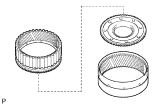 |
Remove the center planetary ring gear and front planetary ring gear flange from the front planetary ring gear.
| 45. REMOVE NO. 1 BRAKE DISC |
 |
Remove the flange, 3 discs and 3 plates from the case.
| 46. INSPECT NO. 1 BRAKE DISC |
|
Replace all discs if one of the following problems is present: 1) a disc, plate or flange is worn or burnt, 2) the lining of a disc is peeled off or discolored, or 3) grooves or printed numbers have even a little bit of damage.
| 47. REMOVE BRAKE PISTON RETURN SPRING SNAP RING |
 |
Using a screwdriver, remove the brake piston return spring snap ring from the case.
| 48. REMOVE BRAKE PISTON RETURN SPRING SUB-ASSEMBLY |
 |
Remove the brake piston return spring and No. 1 the brake piston with the No. 1 brake cylinder from the transmission case.
| 49. INSPECT BRAKE PISTON RETURN SPRING SUB-ASSEMBLY |
 |
Using a vernier caliper, measure the free length of the spring together with the spring seat.
| 50. REMOVE NO. 1 BRAKE PISTON |
 |
Hold the brake piston No. 1 and apply compressed air (392 kPa, 4 kgf/cm2, 57 psi) to the transmission case to remove the No. 1 brake piston.
Remove the 2 O-rings from the No. 1 brake piston.
| 51. REMOVE NO. 2 BRAKE DISC |
 |
Using a screwdriver, remove the snap ring from the case.
 |
Remove the flange, the brake piston return spring, the 3 discs and the 3 plates from the case.
| 52. INSPECT NO. 2 BRAKE DISC |
|
Replace all discs if one of the following problems is present: 1) a disc, plate or flange is worn or burnt, 2) the lining of a disc is peeled off or discolored, or 3) grooves or printed numbers have even a little bit of damage.
| 53. INSPECT NO.2 BRAKE PISTON RETURN SPRING SUB-ASSEMBLY |
 |
Using a vernier calipers, measure the free length of the spring together with the spring seat.
| 54. REMOVE NO. 2 BRAKE PISTON |
 |
Hold the No. 2 brake piston and apply compressed air (392 kPa, 4 kgf/cm2, 57 psi) to the transmission case to remove the No. 2 brake piston.
Remove the 2 O-rings from the No. 2 brake piston.
| 55. REMOVE CENTER PLANETARY GEAR ASSEMBLY |
 |
Remove the center planetary gear assembly, the planetary sun gear and the No. 4 thrust bearing race from the case.
| 56. INSPECT CENTER PLANETARY GEAR ASSEMBLY |
 |
Using a feeler gauge, measure the center planetary gear pinion thrust clearance.
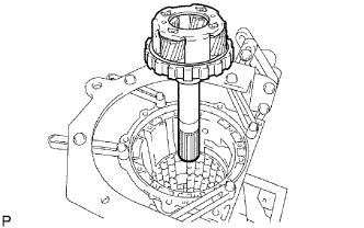
| 57. REMOVE INTERMEDIATE SHAFT |
 |
Using a screwdriver, remove the snap ring from the case.
 |
Remove the intermediate shaft with the No. 3 1- way clutch assembly from the case.
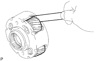
| 58. INSPECT NO. 3 1-WAY CLUTCH ASSEMBLY |
 |
Hold the rear planetary ring gear flange sub-assembly turn the 1-way clutch assembly.
Check that the 1-way clutch assembly turns freely counterclockwise and locks when turned clockwise.
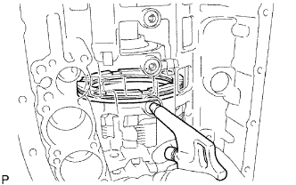
| 59. REMOVE NO. 3 1-WAY CLUTCH ASSEMBLY |
 |
Remove the No. 3 1-way clutch assembly and the 1 way clutch inner race from the intermediate shaft.
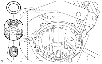
| 60. REMOVE REAR PLANETARY RING GEAR FLANGE SUB-ASSEMBLY |
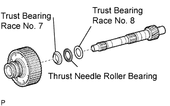 |
Remove the No. 8 thrust bearing race thrust needle roller bearing, the No. 7 thrust bearing race and the planetary ring gear flange from the intermediate shaft.
| 61. INSPECT REAR PLANETARY RING GEAR FLANGE SUB-ASSEMBLY |
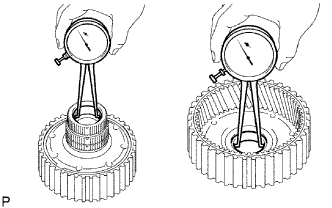 |
Using a dial indicator, measure the inside diameter of the rear planetary ring gear bushing.
| 62. INSPECT INTERMEDIATE SHAFT |
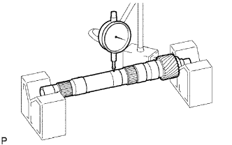 |
Using a dial indicator, check the intermediate shaft runout.
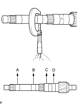 |
Using a micrometer, check the outer diameter of the intermediate shaft positions shown in the diagram.
| 63. REMOVE BRAKE PLATE STOPPER SPRING |
 |
Remove the brake plate stopper spring from the case.
| 64. REMOVE NO. 4 BRAKE DISC |
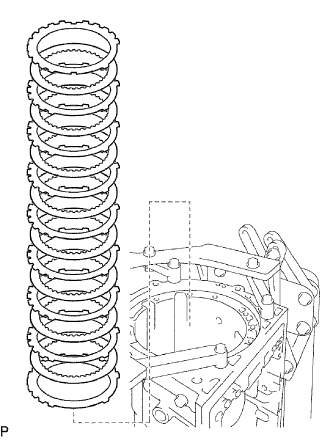 |
Remove the 7 plates, the 8 discs and the 2 flanges from the case.
| 65. INSPECT NO. 4 BRAKE DISC |
|
Replace all discs if one of the following problems is present: 1) a disc, plate or flange is worn or burnt, 2) the lining of a disc is peeled off or discolored, or 3) grooves or printed numbers have even a little bit of damage.
| 66. REMOVE REAR PLANETARY GEAR ASSEMBLY |
 |
Remove the rear planetary gear assembly from the case.
 |
Remove the thrust bearing race No. 9 and the thrust needle roller bearing from the rear planetary gear assembly.
 |
Remove the thrust needle roller bearing from the case.
| 67. INSPECT REAR PLANETARY GEAR ASSEMBLY |
|
Using a dial indicator, measure the inside diameter of the rear planetary ring gear bushing.
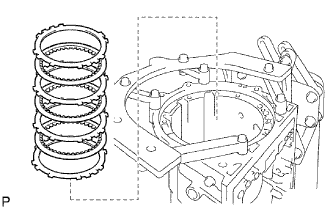
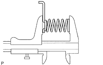
| 68. REMOVE 1ST AND REVERSE BRAKE RETURN SPRING SUB-ASSEMBLY |
 |
Place SST on the spring retainer and compress the brake return spring.
Using SST, remove the snap ring and the brake return spring.
| 69. INSPECT 1ST AND REVERSE BRAKE RETURN SPRING SUB-ASSEMBLY |
 |
Using a vernier caliper, measure the free length of the spring together with the spring seat.
| 70. REMOVE 1ST AND REVERSE BRAKE PISTON |
 |
Hold the No. 2 brake piston and apply compressed air (392 kPa, 4 kgf/cm2, 57 psi) to the transmission case to remove the No. 2 brake piston.
Remove the O-ring from No. 2 brake piston.
| 71. REMOVE BRAKE REACTION SLEEVE |
 |
Using SST, remove the reaction sleeve.
Remove the O-ring from the reaction sleeve.
| 72. REMOVE NO. 4 BRAKE PISTON |
 |
Using SST, remove the No. 4 bbrake piston.
Remove the 2 O-rings from the No. 4 piston.
