AUTOMATIC TRANSMISSION UNIT > REASSEMBLY |
| 1. BEARING POSITION |
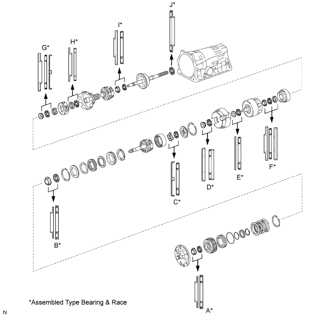
| Mark | Front Race Diameter Inside / Outside | Thrust Bearing Diameter Inside / Outside | Rear Race Diameter Inside / Outside |
| A | 28.45 mm (1.120 in.) / 47.3 mm (1.862 in.) | 29.2 mm (1.15 in.) / 50.2 mm (1.976 in.) | - |
| B | 28.6 mm (1.126 in.) / 46.4 mm (1.827 in.) | 28.9 mm (1.138 in.) / 50.2 mm (1.976 in.) | - |
| C | 33.0 mm (1.299 in.) /50.4 mm (1.984 in.) | 31.4 mm (1.236 in.) / 49.4 mm (1.945 in.) | - |
| D | 37.2 mm (1.465 in.) / 58.8 mm (2.315 in.) | 33.8 mm (1.331 in.) / 50.0 mm (1.969 in.) | - |
| E | 36.8 mm (1.449 in.) / 50.9 mm (2.004 in.) | 33.7 mm (1.327 in.) / 47.6 mm (1.874 in.) | - |
| F | 26.0 mm (1.024 in.) / 48.9 mm (1.925 in.) | 26.0 mm (1.024 in.) / 42.8 mm (1.685 in.) | 26.8 mm (1.055 in.) / 53.67 mm (2.113 in.) |
| G | - | 49.9 mm (.1.965 in.) /64.4 mm (2.535 in.) | 53.4 mm (2.102 in.) / 63.6 mm (2.504 in.) |
| H | 33.7 mm (1.327 in.) / 47.6 mm (1.874 in.) | 35.5 mm (1.398 in.) / 47.7 mm (1.878 in.) | - |
| I | 28.5 mm (1.122 in.) / 44.2 mm (1.740 in.) | 27.7 mm (1.091 in.) / 44.2 mm (1.740 in.) | - |
| J | - | 39.38 mm (1.550 in.) / 58.1 mm (2.287 in.) | - |
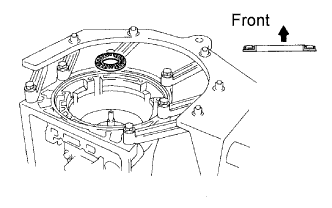
| 2. FIX TRANSMISSION CASE |
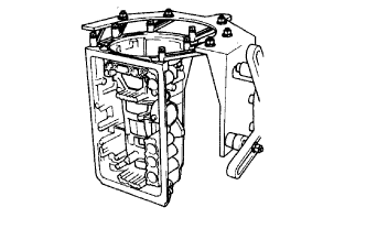 |
Install the transmission case in the overhaul attachment.
| 3. INSTALL NO. 1 1ST AND REVERSE BRAKE PISTON |
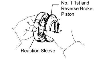 |
Coat 2 new O-rings with ATF.
Install the 2 O-rings on the No. 1 brake piston.
Install the No. 1 brake piston to the reaction sleeve.
| 4. INSTALL BRAKE REACTION SLEEVE |
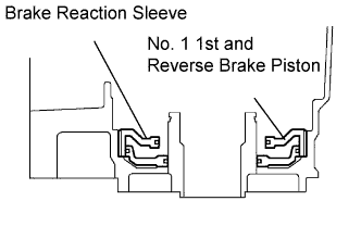 |
Coat a new O-ring with ATF, and install it to the reaction sleeve.
With the No. 1 brake piston underneath (the rear side), install the brake reaction sleeve and No. 1 brake piston to the transmission case.
| 5. INSTALL NO. 2 1ST AND REVERSE BRAKE PISTON |
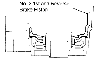 |
Coat a new O-ring with ATF.
Install the O-ring on brake piston.
With the spring seat of the piston facing upward (the front side), place the piston in the transmission case.
| 6. INSTALL 1ST AND REVERSE BRAKE RETURN SPRING SUB-ASSEMBLY |
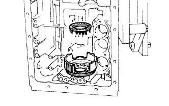 |
Place the No. 2 brake return spring onto the brake piston.
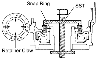 |
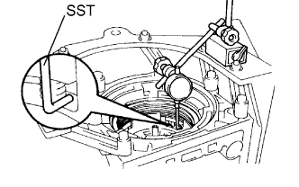
Place SST on the brake return spring, and compress the brae return spring.
Using SST, install the snap ring. Make sure the end gap of the snap ring is not aligned with the spring retainer claw.
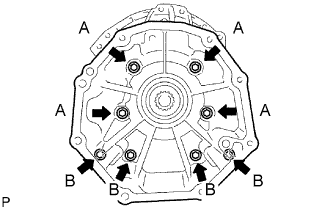
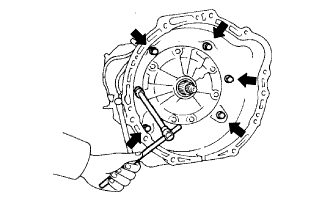
| 7. INSPECT PISTON STROKE OF 1ST AND REVERSE BRAKE |
 |
Make sure the 1st and reverse brake pistons move smoothly when compressed air is applied into the transmission case.
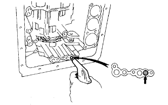
| 8. INSTALL LEAF SPRING |
 |
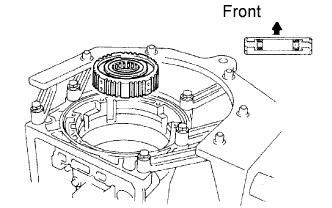
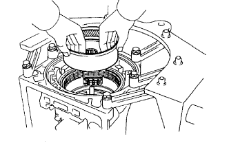
| 9. INSTALL REAR PLANETARY GEAR ASSEMBLY |
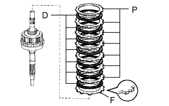 |
Install the flange with the rounded edge facing upward.
Install the 7 discs and 7 plates.
 |
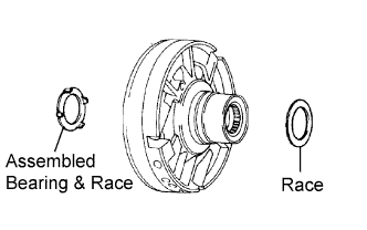
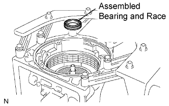
Coat the assembled bearing and race with petroleum jelly, and install it onto the case.
| Item | Inside | Outside |
| Assembled bearing and race | 39.38 mm (1.550 in.) | 58.1 mm (2.287 in.) |
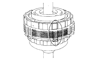 |
Align the teeth on the flange, discs and plates.
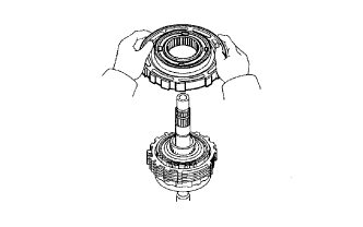 |
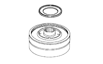
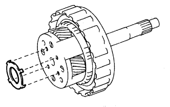
Face the snap ring upward (front side), and install the 2nd brake drum to the planetary gear.
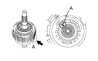 |
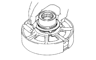
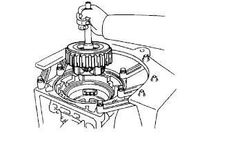
Align the splines of the transmission case with the assembled rear planetary gear and 1st and reverse brake with the output shaft, indicated by A.
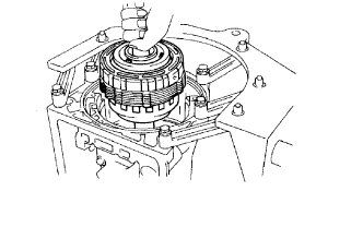 |
Install the assembled output shaft.
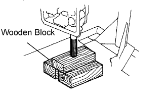 |
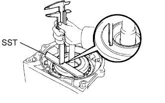
Reset the output shaft on wooden blocks.
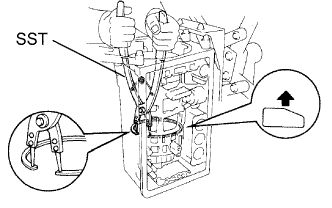 |
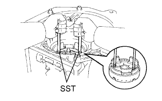
Using SST, Install the snap ring.
| 10. INSPECT PACK CLEARANCE OF 1ST AND REVERSE BRAKE |
 |
Using a feeler gauge, measure the clearance between the plate and 2nd brake drum.
| No. | Thickness | No. | Thickness |
| 67 | 5.4mm (0.213 in.) | 52 | 4.6 mm (0.181 in.) |
| 66 | 5.2 mm (0.205 in.) | 53 | 4.4 mm (0.173 in.) |
| 50 | 5.0 mm (0.197 in.) | 54 | 4.2 mm (0.165 in.) |
| 51 | 4.8 mm (0.189 in.) | 55 | 4.0 mm (0.157 in.) |
| 11. INSTALL 2ND BRAKE PISTON SLEEVE |
 |
| 12. INSTALL BRAKE DRUM GASKET |
 |
Coat a new gasket with ATF, and install the brake drum gasket.
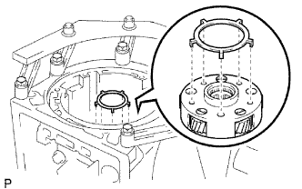
| 13. INSTALL NO. 1 ONE-WAY CLUTCH |
 |
Install the thrust washer onto the 2nd brake piston sleeve.
 |
Install the No. 1 one-way clutch as shown in the illustration.
| 14. INSTALL 1ST AND REVERSE BRAKE CLUTCH DISC |
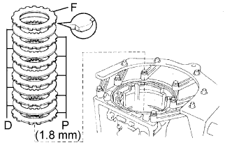 |
Install the 1.8 mm (0.071 in.) thick plate with the rounded edge side of the plate facing the disc.
Install the flange, 5 plates and 5 discs.
 |
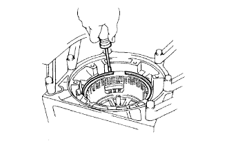
Using a screwdriver, install the snap ring.
| 15. INSPECT PACK CLEARANCE OF 2ND BRAKE |
 |
Using a feeler gauge, measure the clearance between the snap ring and flange.
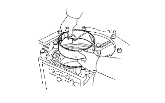
| 16. INSTALL PLANETARY SUN GEAR ASSEMBLY AND ONE-WAY CLUTCH ASSEMBLY |
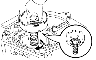 |
While turning the sun gear clockwise, install it into the one-way clutch.
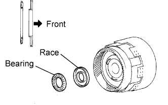
| 17. INSTALL FRONT PLANETARY GEAR |
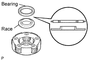 |
Coat the bearing and race with petroleum jelly, and install them onto the planetary gear.
| Item | Inside | Outside |
| Bearing | 35.5 mm (1.398 in.) | 47.7 mm (1.878 in.) |
| Race | 33.7 mm (1.327 in.) | 47.6 mm (1.874 in.) |
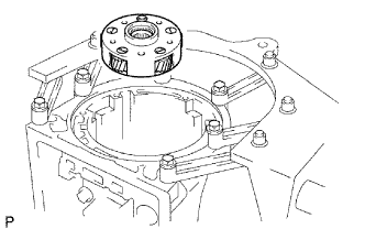 |
Install the planetary gear to the sun gear input drum.
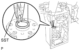 |
Using SST, install the snap ring.
Remove the wooden blocks under the output shaft.
 |
Coat the race with petroleum jelly, and install it onto the planetary gear.
| Item | Inside | Outside |
| Race | 53.4 mm (2.102 in.) | 63.6 mm (2.504 in.) |
| 18. INSTALL 2ND COAST BRAKE BAND |
 |
Install the brake band to the case.
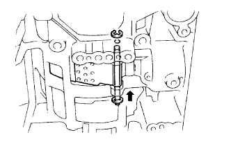 |
Install the E-ring to the pin.
Install the pin through the brake band.
| 19. INSTALL DIRECT CLUTCH ASSEMBLY |
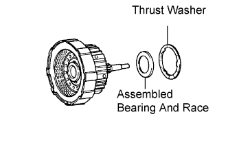 |
Install the assembled bearing and race and thrust washer to the forward clutch.
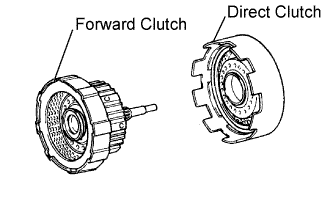 |
Install the direct clutch to the forward clutch.
| 20. INSTALL FRONT PLANETARY RING GEAR |
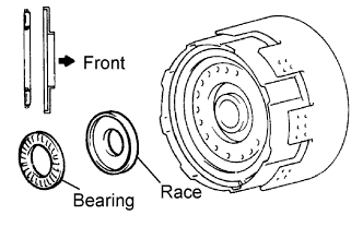 |
Coat the race with petroleum jelly, and install them onto the forward clutch.
| Item | Inside | Outside |
| Bearing | 26.0 mm (1.024 in.) | 42.8 mm (1.685 in.) |
| Race | 26.0 mm (1.024 in.) | 48.9 mm (1.925 in.) |
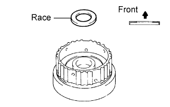 |
Coat the race with petroleum jelly, and install it onto the front planetary ring gear.
| Item | Inside | Outside |
| Race | 26.8 mm (1.055 in.) | 53.67 mm (2.113 in.) |
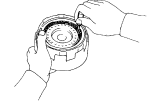 |
Align the flukes of the discs in the forward clutch.
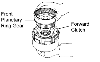 |
Align the splines of the planetary ring gear with the flukes of the discs and install the planetary ring gear to the forward clutch.
| 21. INSTALL FORWARD CLUTCH ASSEMBLY |
 |
Coat the bearing and race with petroleum jelly, and install them onto the ring gear.
| Item | Inside | Outside |
| Bearing | 49.9 mm (1.965 in.) | 64.4 mm (2.535 in.) |
| Race | 53.4 mm (2.102 in.) | 63.6 mm (2.504 in.) |
 |
Install the assembled direct clutch, forward clutch and front planetary ring gear into the transmission case.
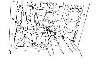
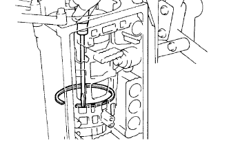
 |
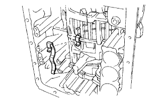
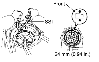
Using a vernier caliper, measure the distance between the sun gear input drum and direct clutch drum as shown in the illustration.
 |
Coat the assembled bearing and race with petroleum jelly and install it onto the forward clutch.
| Item | Inside | Outside |
| Assembled bearing and race | 33.7 mm (1.327 in.) | 47.6 mm (1.874 in.) |
| 22. INSTALL 2ND COAST BRAKE PISTON ASSEMBLY |
 |
Coat 2 new O-rings with ATF, and install them to the cover.
Install the spring, the piston assembly and cover to the case.
 |
Using SST, install the snap ring.
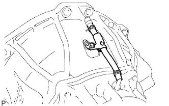
| 23. INSPECT PISTON STROKE OF 2ND COAST BRAKE |
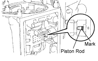 |
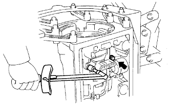
Place a mark on the 2nd coast brake piston rod.
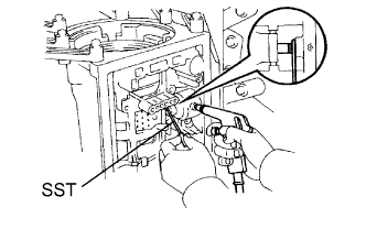 |
Using SST, measure the stroke while applying and releasing compressed air (392 kPa (4.0 kgf/cm2, 57 psi)).
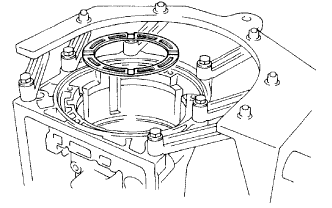
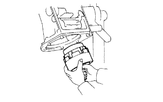
| 24. INSTALL OVERDRIVE BRAKE ASSEMBLY |
 |
Coat the assembled bearing and race and race with petroleum jelly, and install it onto the overdrive brake assembly.
| Item | Inside | Outside |
| Race | 36.8 mm (1.449 in.) | 50.9 mm (2.004 in.) |
| Assembled bearing and race | 33.8 mm (1.331 in.) | 50.0 mm (1.969 in.) |
 |
Confirm that the thrust washer is installed correctly.
 |
Using 2 bolts of SST, aim the bolt and oil holes of the overdrive rake assembly toward the valve body side, and align them with the bolt holes of the transmission case. Insert the overdrive brake assembly.
Temporarily tighten the 2 bolts.
 |
Using SST, install the snap ring.
 |
Tighten the 2 bolts.
| 25. INSPECT OUTPUT SHAFT |
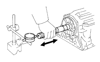 |
Using a dial indicator, measure the end play of the output shaft with hand.
Check that the output shaft rotates smoothly.
| 26. INSTALL OVERDRIVE BRAKE CLUTCH DISC |
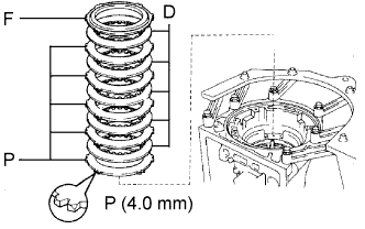 |
Install the 4.0 mm (0.157 in.) thick flange (flat ring) with the rounded edge side of the flange facing the discs.
Install the 5 plates, 5 discs and flange.
 |
Using a screwdriver, install the snap ring.
| 27. INSPECT OVERDRIVE BRAKE PISTON |
 |
Place SST and a dial indicator onto the overdrive brake piston.
 |
Measure the stroke while applying and releasing compressed air (392 kPa (4.0 kgf/cm2, 57 psi)).
| No. | Thickness | No. | Thickness |
| 77 | 3.3 mm (0.130 in.) | 81 | 3.8 mm (0.150 in.) |
| 78 | 3.5 mm (0.138 in.) | 82 | 3.9 mm (0.154 in.) |
| 79 | 3.6 mm (0.142 in.) | 83 | 4.0 mm (0.157 in.) |
| 80 | 3.7 mm (0.146 in.) |
| 28. INSTALL OVERDRIVE PLANETARY RING GEAR |
 |
Coat the race with petroleum jelly, and install it onto the overdrive brake assembly.
| Item | Inside | Outside |
| Race | 37.2 mm (1.465 in.) | 58.8 mm (2.315 in.) |
 |
Install the ring gear.
 |
Coat the assembled bearing and race with petroleum jelly, and install them onto the ring gear.
| Item | Inside | Outside |
| Assembled bearing and race | 31.4 mm (1.236 in.) | 49.4 mm (1.945 in.) |
 |
Coat the race with petroleum jelly, and install it onto the planetary gear.
| Item | Inside | Outside |
| Race | 24.7 mm (0.972 in.) | 41.8 mm (1.646 in.) |
 |
Install the overdrive planetary gear, overdrive direct clutch and one-way clutch.
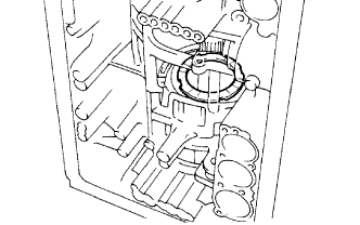
 |
Place SST on the transmission case.
Using a vernier caliper, measure the distance between the top of SST and clutch drum.
 |
Coat the assembled bearing and race with petroleum jelly, and install it onto the overdrive direct clutch.
| Item | Inside | Outside |
| Assembled bearing and race | 29.2 mm (1.150 in.) | 50.2 mm (1.976 in.) |
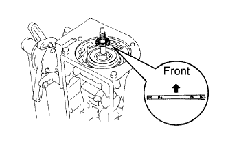
| 29. INSTALL OIL PUMP ASSEMBLY |
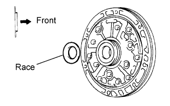 |
Coat the race with petroleum jelly, and install it onto the oil pump.
| Item | Inside | Outside |
| Race | 28.45 mm (1.120 in.) | 47.3 mm (1.862 in.) |
Coat a new O-ring with ATF, and install it around the pump body.
Place the oil pump through the input shaft, and align the bolt holes of the pump body with the transmission case.
Hold the input shaft, and lightly press the oil pump body to slide the oil seal rings into the overdrive direct clutch drum.
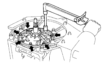 |
Install the 7 bolts.
| 30. INSPECT INPUT SHAFT SUB-ASSEMBLY |
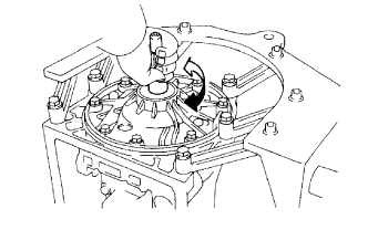 |
Make sure the input shaft rotates smoothly.
| 31. INSTALL TRANSMISSION CASE PLUG |
 |
Coat a new O-ring with ATF, and install it to the plug.
Install the plug to the case with the bolt.
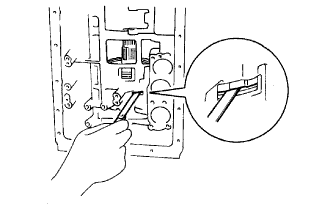
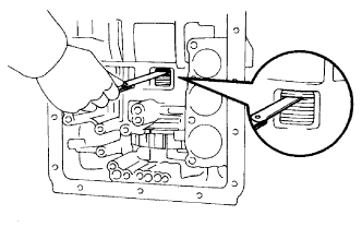
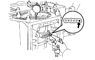
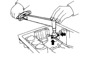
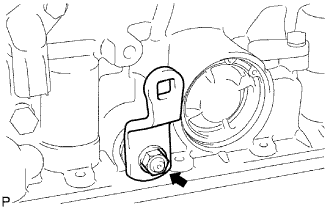
| 32. INSPECT INDIVIDUAL PISTON OPERATION |
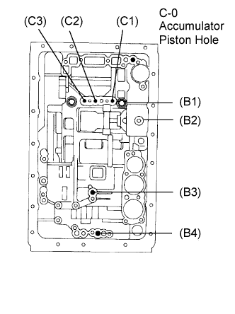 |
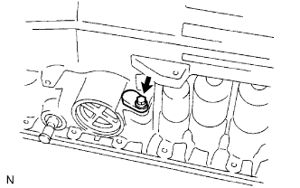
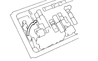
Check the operating sound while applying compressed air into the oil hole indicated in the illustration.
Overdrive direct clutch (C1)
Direct clutch (C2)
Forward clutch (C3)
Overdrive brake (B1)
2nd coast brake (B2)
2nd brake (B3)
1st and reverse brake (B4)
| 33. INSTALL MANUAL VALVE LEVER SHAFT OIL SEAL |
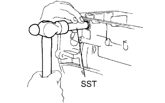 |
Using SST and a hammer, tap in 2 new oil seals.
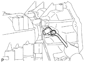
| 34. INSTALL MANUAL VALVE LEVER SHAFT |
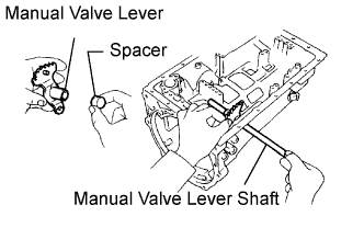 |
Install a new spacer to the manual valve lever.
Install the manual valve lever shaft to the transmission case through the manual valve lever.
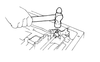 |
Using a hammer, tap in a new spring pin.
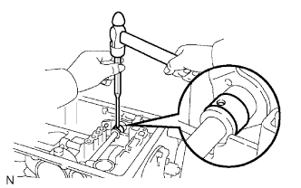 |
Align the manual valve lever indentation with the spacer hole, and stake them with the punch.
Make sure that the shaft rotates smoothly.
| 35. INSTALL PARKING LOCK PAWL SHAFT |
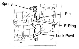 |
Install the E-ring to the shaft.
Install the parking lock pawl, shaft and spring.
| 36. INSTALL PARKING LOCK ROD |
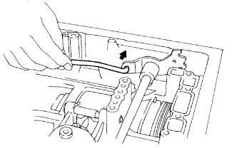 |
Connect the parking lock rod to the manual valve lever.
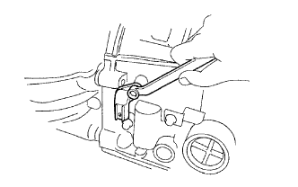
| 37. INSTALL PARKING LOCK PAWL BRACKET |
 |
Place the parking lock pawl bracket onto the transmission case and install the 3 bolts.
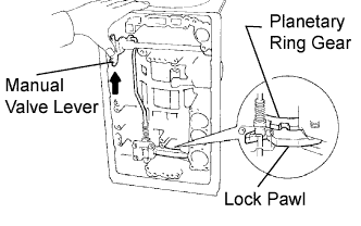 |
Shift the manual valve lever to the P position, and confirm that the planetary ring gear is correctly locked up by the lock pawl.
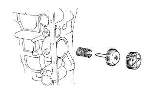
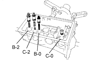
| 38. INSTALL C-0 ACCUMULATOR PISTON |
 |
Coat a new O-ring with ATF, and install it to the piston.
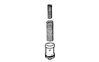 |
Install the 2 springs and accumulator piston to the hole.
| Free Length | Outer Diameter | Color |
| 51.5 mm (2.028 in.) | 14.02 mm (0.552 in.) | Red |
| Free Length | Outer Diameter | Color |
| 79.9 mm (3.146 in.) | 20.9 mm (0.823 in.) | Light Blue |
| 39. INSTALL B-0 ACCUMULATOR PISTON |
|
Coat 2 new O-rings with ATF, and install them to the piston.
 |
Install the spring and accumulator piston to the hole.
| Free Length | Outer Diameter | Color |
| 62.0 mm (2.441 in.) | 16.0 mm (0.630 in.) | Green |
| 40. INSTALL C-2 ACCUMULATOR PISTON |
|
Coat 2 new O-rings with ATF, and install them to the piston.
 |
Install the 2 springs and accumulator piston to the hole.
| Free Length | Outer Diameter | Color |
| 42.1 mm (1.657 in.) | 14.7 mm (0.579 in.) | Pink |
| Free Length | Outer Diameter | Color |
| 68.53 mm (2.698 in.) | 20.2 mm (0.795 in.) | Blue |
| 41. INSTALL B-2 ACCUMULATOR PISTON |
|
Coat 2 new O-rings with ATF, and install them to the piston.
 |
Install the spring and accumulator piston to the hole.
| Free Length | Outer Diameter | Color |
| 70.5 mm (2.776 in.) | 19.9 mm (0.784 in.) | Light Grey |
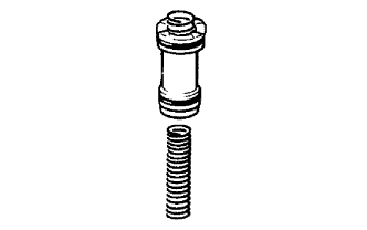
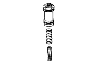
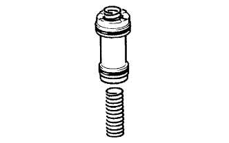
| 42. INSTALL CHECK BALL BODY |
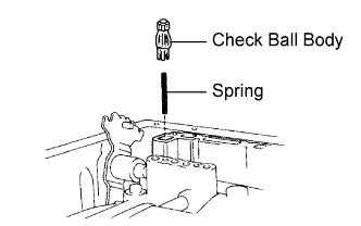 |
Install the spring and check ball body.
| 43. INSTALL TRANSMISSION VALVE BODY ASSEMBLY |
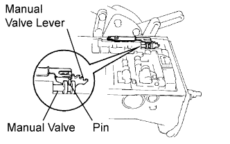 |
Align the groove of the manual with the pin of the lever.
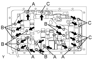 |
Install the 20 bolts.
| 44. INSTALL TRANSMISSION WIRE |
 |
Coat a new O-ring with ATF, and install it to the transmission wire.
Install the transmission wire to the case, and install the stopper plate with the bolt.
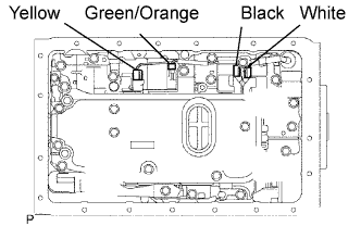 |
Connect the connectors to the shift solenoid valves.
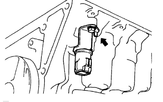
| 45. INSTALL VALVE BODY OIL STRAINER ASSEMBLY |
 |
Using a plastic-faced hammer, install the pipe as shown in the illustration.
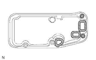 |
Install 5 new gaskets on the oil strainer.
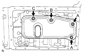 |
Install the oil strainer with the 4 bolts.
| 46. INSTALL OIL CLEANER MAGNET |
 |
Install the 3 magnets.
| 47. INSTALL AUTOMATIC TRANSMISSION OIL PAN SUB-ASSEMBLY |
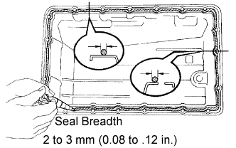 |
Remove any FIPG material.
Apply FIPG to the oil pan.
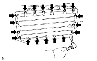 |
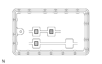
Install the oil pan with the 19 bolts.
| 48. INSTALL SENSOR ROTOR |
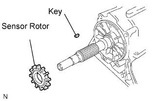 |
Install the key on the output shaft.
Align the groove of the sensor rotor with the key, and install the sensor rotor.
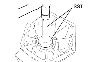
 |
Using snap ring pliers, install the snap ring.
| 49. INSTALL TRANSFER CASE ADAPTOR REAR OIL SEAL |
 |
Using SST and a hammer, install a new oil seal.
| 50. INSTALL REAR ADAPTOR TRANSFER |
 |
Install the rear adaptor transfer and gasket.
Install the 8 bolts.
| 51. INSTALL AUTOMATIC TRANSMISSION HOUSING |
 |
Clean the threads of the bolts and case with white gasoline.
Apply seal packing or equivalent to the 6 bolts.
Install the transmission housing with the 6 bolts.
| 52. INSTALL NO. 2 VEHICLE SPEED SENSOR |
 |
Install a new O-ring to the sensor.
Install the sensor with the bolt.
| 53. INSTALL OVERDRIVE DIRECT CLUTCH SPEED SENSOR |
 |
Install a new O-ring to the sensor.
Install the speed sensor with the bolt.
| 54. INSTALL OIL COOLER TUBE UNION |
 |
Coat 2 new O-rings with ATF, and install them to each tube union.
| 55. INSTALL AUTOMATIC TRANSMISSION FLUID TEMPERATURE SENSOR |
 |
Coat a new O-ring with ATF, and install it to the sensor.
Install the sensor.
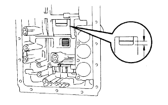
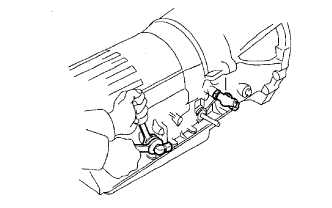
| 56. INSTALL PARK/NEUTRAL POSITION SWITCH ASSEMBLY |
 |
Install the park/neutral position switch onto the manual valve lever shaft, and temporarily install the adjusting bolt.
Install the grommet and a new lock washer. Install and torque the nut.
 |
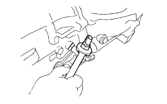
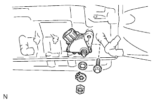
Push the control shaft rearward as much as possible.
Return the control shaft lever 2 notches to the N position.
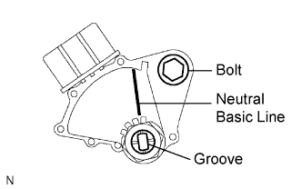 |
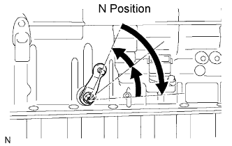
Align the neutral basic line with the switch groove, as shown in the illustration, and tighten the adjusting bolt.
| 57. INSTALL TRANSMISSION CONTROL SHAFT LEVER LH |
 |
Install the control shaft lever with the washer and nut.
| 58. INSTALL BREATHER HOSE |
 |
Install the breather hose.
| 59. INSTALL DRAIN PLUG SUB-ASSEMBLY |
