AUTOMATIC TRANSMISSION UNIT > DISASSEMBLY |
| 1. REMOVE DRAIN PLUG SUB-ASSEMBLY |
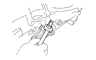
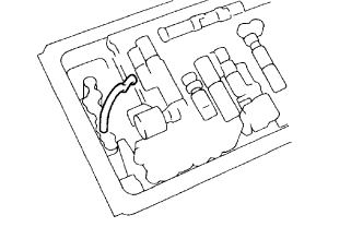
| 2. REMOVE BREATHER HOSE |
 |
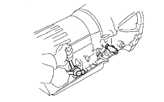
| 3. REMOVE TRANSMISSION CONTROL SHAFT LEVER LH |
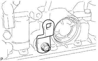 |
Remove the nut, washer and control shaft lever.
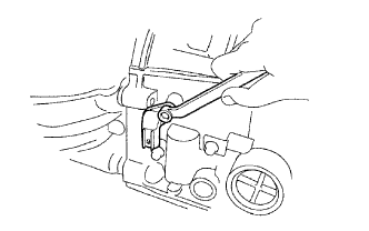
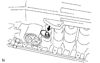
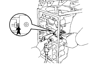
| 4. REMOVE PARK/NEUTRAL POSITION SWITCH ASSEMBLY |
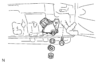 |
Using a screwdriver, unstake the lock washer.
Remove the nut, lock washer and grommet.
Remove the bolt and park/neutral position switch.
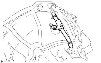
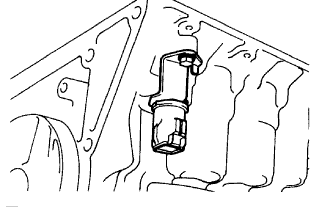
| 5. REMOVE ATF TEMPERATURE SENSOR |
 |
Remove the bolt and sensor.
Remove the O-ring from the sensor.
| 6. REMOVE OIL COOLER TUBE UNION |
 |
Remove the 2 tube unions.
Remove the O-rings from each tube union.
| 7. REMOVE OVERDRIVE DIRECT CLUTCH SPEED SENSOR |
 |
Remove the bolt and sensor.
Remove the O-ring from the sensor.
| 8. REMOVE NO. 2 VEHICLE SPEED SENSOR |
 |
Remove the bolt and sensor.
Remove the O-ring from the sensor.
| 9. REMOVE AUTOMATIC TRANSMISSION HOUSING |
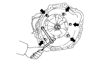 |
Remove the 6 bolts.
Remove the transmission housing.
| 10. FIX TRANSMISSION CASE |
 |
Install the transmission case on the overhaul attachment.
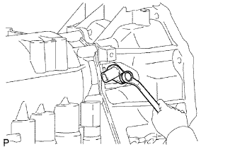
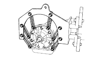
| 11. REMOVE REAR ADAPTOR TRANSFER |
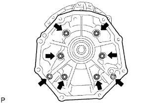 |
Remove the 8 bolts.
Remove the rear adaptor transfer.
| 12. REMOVE TRANSFER CASE ADAPTOR REAR OIL SEAL |
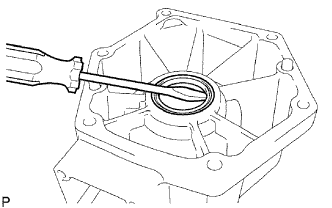 |
Using a screwdriver, pry out the oil seal.
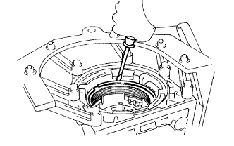
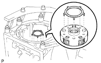
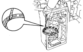
| 13. REMOVE SENSOR ROTOR |
 |
Using a snap ring expander, remove the snap ring.
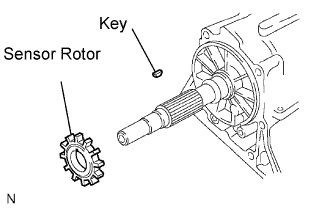 |
Remove the sensor rotor and key.
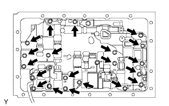
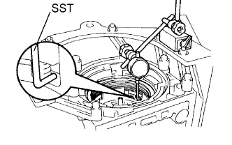
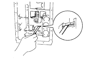
| 14. REMOVE AUTOMATIC TRANSMISSION OIL PAN SUB-ASSEMBLY |
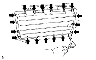 |
Remove the 19 bolts.
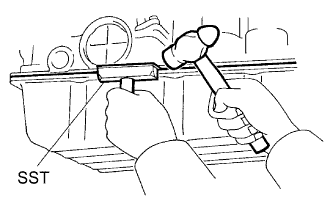 |
Install the blade of SST between the transmission case and the oil pan, and cut off the applied sealer.
Remove the pan by lifting the transmission case.
| 15. INSPECT AUTOMATIC TRANSMISSION OIL PAN SUB-ASSEMBLY |
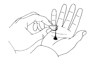 |
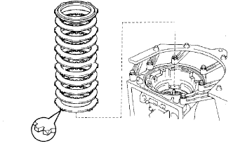
Remove the magnets and use them to collect steel particles.
Carefully look at the foreign matter and particles in the pan and on the magnets to anticipate the type of wear you will find in the transmission.
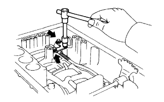
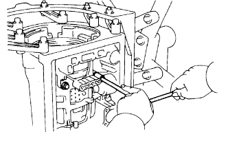
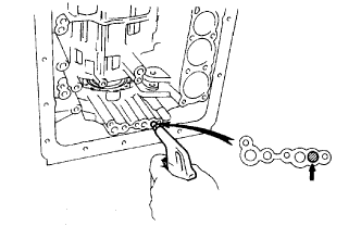
| 16. REMOVE VALVE BODY OIL STRAINER ASSEMBLY |
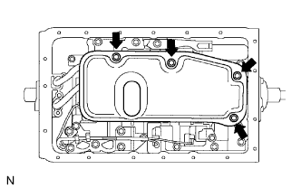 |
Remove the 4 bolts holding the oil strainer to the valve body.
Remove the oil strainer and 5 gaskets.
 |
Pry the pipe ends with a large screwdriver and remove the pipe.
| 17. REMOVE TRANSMISSION WIRE |
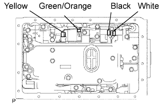 |
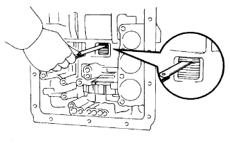
Disconnect the 4 connectors from the shift solenoid valves.
 |
Remove the bolt and stopper plate from the case.
Pull out the transmission wire from the transmission case.
Remove the O-ring from the transmission wire.
| 18. REMOVE TRANSMISSION VALVE BODY ASSEMBLY |
 |
Remove the 20 bolts and valve body.
| 19. REMOVE CHECK BALL BODY |
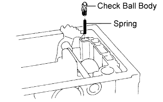 |
Remove the check ball body and spring.
| 20. REMOVE B-2 ACCUMULATOR PISTON |
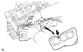 |
Apply compressed air to the oil hole to remove the B-2 accumulator piston and spring.
Remove the 2 O-rings from the piston.
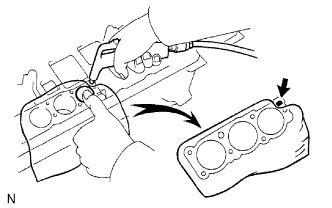
| 21. REMOVE C-2 ACCUMULATOR PISTON |
 |
Apply compressed air to the oil hole to remove the C-2 accumulator piston and spring.
Remove the 2 O-rings from the piston.
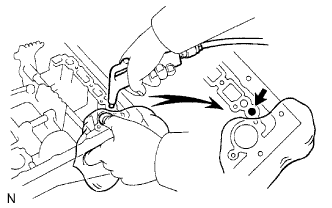
| 22. REMOVE B-0 ACCUMULATOR PISTON |
 |
Apply compressed air to the oil hole to remove the B-0 accumulator piston and spring.
Remove the 2 O-rings from the piston.
| 23. REMOVE C-0 ACCUMULATOR PISTON |
 |
Apply compressed air to the oil hole to remove the C-0 accumulator piston.
Remove the O-ring from the piston.
| 24. REMOVE TRANSMISSION CASE PLUG |
 |
Remove the bolt and pull out the plug.
Remove the O-ring from the plug.
| 25. REMOVE PARKING LOCK PAWL BRACKET |
 |
Remove the 3 bolts and bracket.
| 26. REMOVE PARKING LOCK ROD |
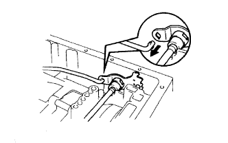 |
Disconnect the parking lock rod from manual valve lever.
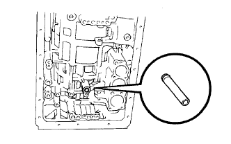
| 27. REMOVE PARKING LOCK PAWL SHAFT |
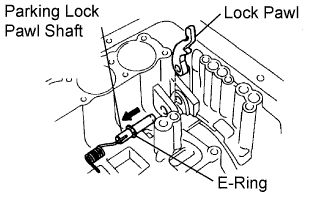 |
Pull out the parking lock pawl shaft from the front side, then remove the lock pawl and spring.
Remove the E-ring from the shaft.
| 28. REMOVE MANUAL VALVE LEVER SHAFT |
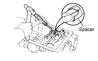 |
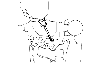
Using a hammer and screwdriver, cut off the spacer and remove the it from the shaft.
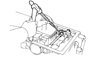 |
Using a pin punch and hammer, tap out the spring pin.
Pull out the manual valve lever shaft through the case, and remove the manual valve lever.
| 29. REMOVE MANUAL VALVE LEVER SHAFT OIL SEAL |
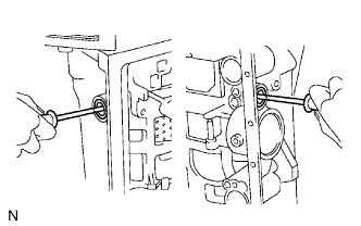 |
Using a screwdriver, pry out the 2 oil seals.
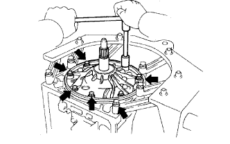
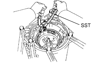
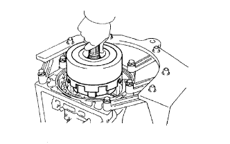
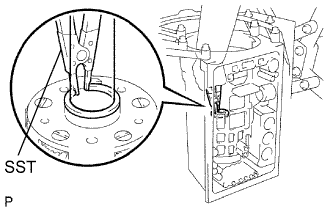
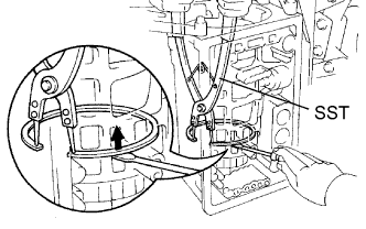
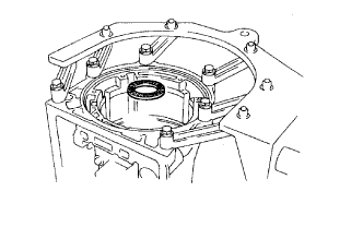
| 30. REMOVE OIL PUMP ASSEMBLY |
 |
Stand up the transmission.
Remove the 7 bolts from the transmission case.
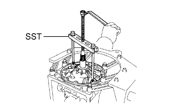 |
Using SST, remove the oil pump.
Remove the O-ring from the oil pump.
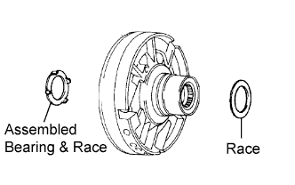
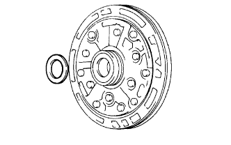 |
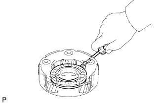
Remove the race from the oil pump.
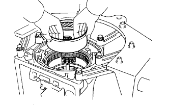
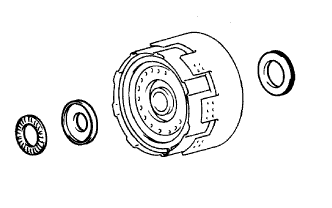
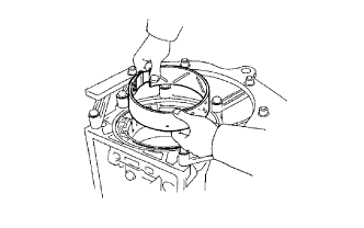
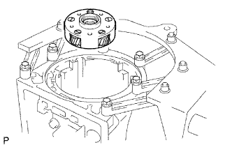
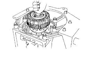
| 31. REMOVE OVERDRIVE PLANETARY GEAR ASSEMBLY AND ONE-WAY CLUTCH ASSEMBLY |
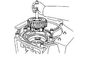 |
Remove the planetary gear, direct clutch and one-way clutch from the transmission case.
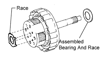 |
Remove the race and assembled bearing and race.
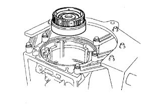
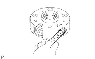
| 32. REMOVE OVERDRIVE PLANETARY RING GEAR |
 |
Remove the ring gear from the transmission case.
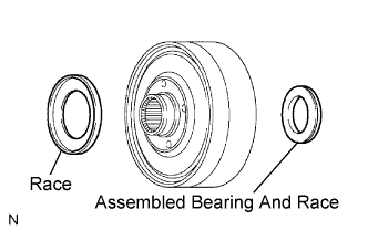 |
Remove the assembled bearing and race and race from the overdrive planetary ring gear.
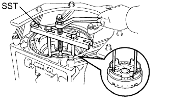
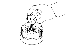
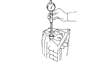
| 33. INSPECT OVERDRIVE BRAKE PISTON |
 |
Place SST and a dial indicator onto the overdrive brake piston.
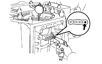 |
Measure the stroke while applying and releasing compressed air (392 kPa (4.0 kgf/cm2, 57 psi)).
| No. | Thickness | No. | Thickness |
| 77 | 3.3 mm (0.130 in.) | 81 | 3.8 mm (0.150 in.) |
| 78 | 3.5 mm (0.138 in.) | 82 | 3.9 mm (0.154 in.) |
| 79 | 3.6 mm (0.142 in.) | 83 | 4.0 mm (0.157 in.) |
| 80 | 3.7 mm (0.146 in.) |
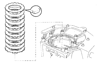
| 34. REMOVE OVERDRIVE BRAKE CLUTCH DISC |
 |
Using a screwdriver, pry out the a snap ring.
 |
Remove the overdrive brake pack.
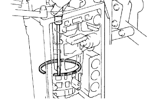
| 35. INSPECT PISTON STROKE OF 2ND COAST BRAKE |
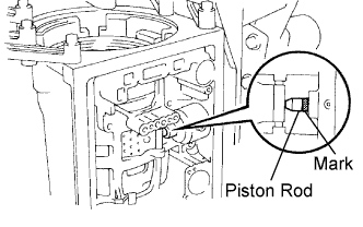 |
Using a water proof pen, place a mark on the 2nd coast brake piston rod as shown in the illustration.
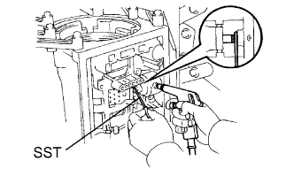 |
Using SST, measure the piston stroke while applying and releasing a compressed air (392 kPa (4.0 kgf/cm2, 57 psi)).
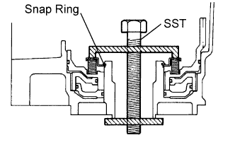
| 36. REMOVE OVERDRIVE SUPPORT ASSEMBLY |
 |
Remove the 2 bolts holding the overdrive brake assembly to the case.
 |
Using SST, remove the snap ring.
 |
Using SST, remove the overdrive brake assembly.
 |
Remove the assembled bearing and race and race from the overdrive brake assembly.
| 37. REMOVE 2ND COAST BRAKE PISTON ASSEMBLY |
 |
Using SST, remove the snap ring.
 |
Apply compressed air to the oil hole to remove the 2nd coast brake cover, piston assembly and spring.
Remove the 2-O-rings from the cover.
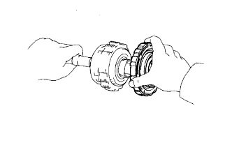
| 38. REMOVE DIRECT CLUTCH ASSEMBLY |
 |
Remove the direct clutch and forward clutch from the case.
 |
Remove the 2 bearings and races.
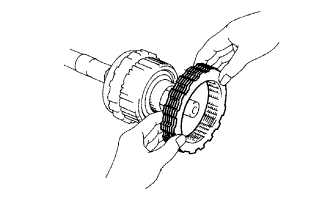
| 39. REMOVE FORWARD CLUTCH ASSEMBLY |
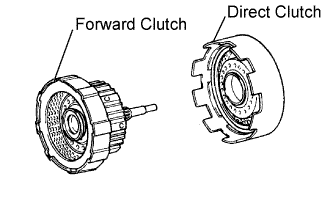 |
Remove the direct clutch from the forward clutch.
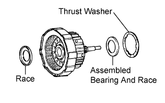 |
Remove the assembled bearing and race, thrust washer and race from the forward clutch.
| 40. REMOVE 2ND COAST BRAKE BAND |
 |
Using a screwdriver, pry out the E-ring from the pin.
 |
Remove the 2nd coast brake band from the case.
| 41. REMOVE FRONT PLANETARY RING GEAR |
 |
Remove the planetary ring gear from the case.
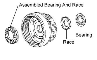 |
Remove the assembled bearing and race, bearing and race from the planetary ring gear.
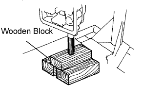 |
With wooden blocks or equivalent under the output shaft, stand the transmission on the output shaft.
| 42. INSPECT FRONT PLANETARY RING GEAR |
 |
Using a dial indicator, measure the inside diameter of the planetary ring gear bush.
| 43. REMOVE FRONT PLANETARY GEAR |
 |
Remove the race from the planetary gear.
 |
Using SST, remove the snap ring.
 |
Remove the planetary gear from the case.
 |
Using a screwdriver, remove the bearing and race from the planetary gear.
| 44. INSPECT FRONT PLANETARY PINION GEAR THRUST CLEARANCE |
 |
Using a feeler gauge, measure the pinion gear thrust clearance.
| 45. REMOVE PLANETARY SUN GEAR ASSEMBLY AND ONE WAY CLUTCH ASSEMBLY |
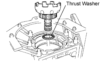 |
Remove the sun gear and one-way clutch from the case.
Remove the thrust washer.
| 46. INSPECT PACK CLEARANCE OF 2ND BRAKE |
 |
Using a feeler gauge, measure the clearance between the snap ring and flange.
| 47. REMOVE 1ST AND REVERSE BRAKE CLUTCH DISC |
 |
Using a screwdriver, pry out the snap ring.
 |
Remove the flange, plates and discs as a set.
| 48. INSPECT PACK CLEARANCE OF 1ST AND REVERSE BRAKE |
 |
Using a feeler gauge, measure the clearance between the plate and 2nd brake drum.
| No. | Thickness | No. | Thickness |
| 67 | 5.4mm (0.213 in.) | 52 | 4.6 mm (0.181 in.) |
| 66 | 5.2 mm (0.205 in.) | 53 | 4.4 mm (0.173 in.) |
| 50 | 5.0 mm (0.197 in.) | 54 | 4.2 mm (0.165 in.) |
| 51 | 4.8 mm (0.189 in.) | 55 | 4.0 mm (0.157 in.) |
| 49. REMOVE 2ND BRAKE PISTON SLEEVE |
 |
Using a screwdriver, remove the sleeve.
| 50. REMOVE REAR PLANETARY GEAR ASSEMBLY |
 |
Using SST and a screwdriver, remove the snap ring.
 |
Remove the rear planetary, 2nd brake drum, 1st and reverse brake pack, No. 2 one-way clutch and output shaft.
 |
Remove the assembled thrust bearing and race from the case.
 |
Remove the 2nd brake drum.
 |
Remove the cushion plate, flange, plates and discs of the 1st and reverse brake.
| 51. REMOVE LEAF SPRING |
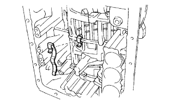 |
| 52. INSPECT 1ST AND REVERSE BRAKE CLUTCH DISC |
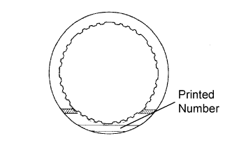 |
Replace all discs if one of the following problems is present: 1) a disc, plate or flange is worn or burnt, 2) the lining of a disc is peeled off or discolored, or 3) grooves or printed numbers have even a little bit of damage.
| 53. REMOVE BRAKE DRUM GASKET |
 |
| 54. INSPECT PISTON STROKE OF 1ST AND REVERSE BRAKE |
 |
Make sure the 1st and reverse brake pistons move smoothly when applying and releasing compressed air into the transmission case.
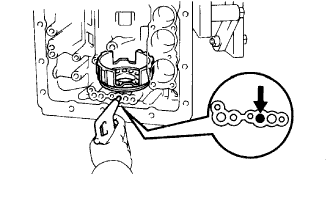
| 55. REMOVE 1ST AND REVERSE BRAKE RETURN SPRING SUB-ASSEMBLY |
 |
Place SST on the 1st and reverse brake return spring, and compress the brake return spring.
Using SST, remove the snap ring and brake return spring.
Hold the No. 2 1st and reverse brake piston by hand, and apply compressed air to the transmission case to remove the No. 2 1st and reverse brake piston.
| 56. INSPECT 1ST AND REVERSE BRAKE RETURN SPRING SUB-ASSEMBLY |
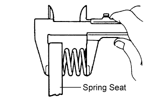 |
Using a vernier caliper, measure the free length of the spring together with the spring seat.
| 57. REMOVE 1ST AND REVERSE BRAKE PISTON NO. 2 |
 |
Hold the No. 2 1st and reverse brake piston and apply compressed air into the transmission case to remove the brake piston.
Remove the O-ring from the brake piston.
| 58. REMOVE BRAKE REACTION SLEEVE |
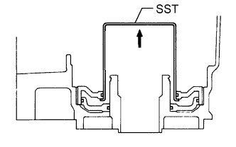 |
Using SST, remove the sleeve.
Remove the 2 O-rings from the sleeve.
| 59. REMOVE NO. 1 1ST AND REVERSE BRAKE PISTON |
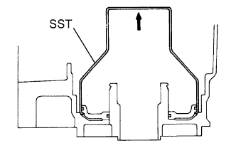 |
Using SST, remove the brake piston.
Remove the 2 O-rings from the brake piston.
| 60. INSPECT TRANSMISSION CASE BUSHING |
 |
Using a cylinder gauge, measure the inside diameter of the transmission case rear bush.
