CLUTCH UNIT > REMOVAL |
| 1. DISCONNECT CABLE FROM NEGATIVE BATTERY TERMINAL |
| 2. REMOVE NO. 1 ENGINE COVER SUB-ASSEMBLY (4WD) |
| 3. REMOVE NO. 2 ENGINE COVER SUB-ASSEMBLY (4WD) |
| 4. REMOVE FRONT PROPELLER SHAFT ASSEMBLY (4WD) |
| 5. REMOVE REAR PROPELLER SHAFT ASSEMBLY |
| 6. REMOVE MANUAL TRANSMISSION UNIT ASSEMBLY |
| 7. REMOVE CLUTCH RELEASE BEARING ASSEMBLY |
| 8. REMOVE CLUTCH RELEASE FORK BOOT |
| 9. REMOVE CLUTCH RELEASE FORK SUB-ASSEMBLY |
| 10. REMOVE RELEASE BEARING HUB CLIP |
| 11. REMOVE RELEASE FORK SUPPORT |
Remove the release fork support from the manual transmission unit.
| 12. REMOVE CLUTCH COVER ASSEMBLY |
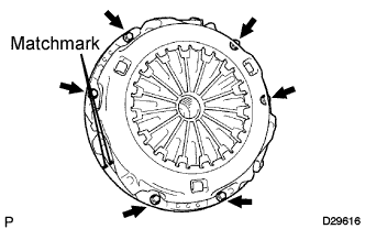 |
Place matchmarks on the clutch cover and flywheel.
Loosen each set bolt one turn at a time until spring tension is released.
Remove the 6 set bolts and pull off the clutch cover.
| 13. REMOVE CLUTCH DISC ASSEMBLY |
| 14. INSPECT INPUT SHAFT FRONT BEARING |
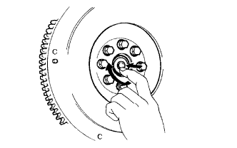 |
Turn the bearing by hand by applying rotational force.
If the bearing sticks or has much resistance, replace the input shaft bearing.
| 15. REMOVE INPUT SHAFT FRONT BEARING |
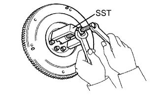 |
Remove any 2 diametrically opposite bolts.
Using SST, remove the input shaft bearing.
| 16. INSPECT CLUTCH DISC ASSEMBLY |
 |
Using a vernier caliper, measure the rivet head depth.
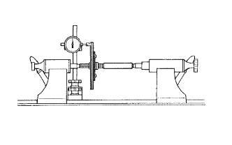 |
Install the clutch disc to the transmission unit.
Using a dial indicator, check the disc runout.
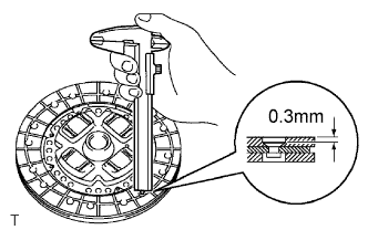
| 17. INSPECT CLUTCH COVER ASSEMBLY |
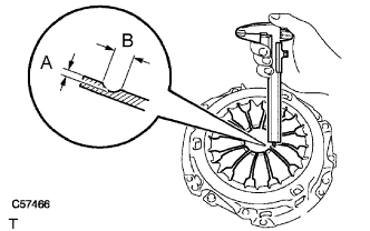 |
Using a vernier caliper, measure the depth and width of the worn areas of the diaphragm spring.
| Measurement | Maximum |
| A (Depth) | 0.5 mm (0.020 in.) |
| B (Width) | 6.0 mm (0.236 in.) |
| 18. INSPECT FLYWHEEL SUB-ASSEMBLY |
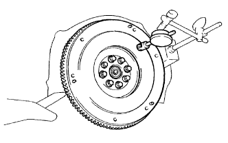 |
Using a dial indicator, measure the flywheel runout.
| 19. INSPECT CLUTCH RELEASE BEARING ASSEMBLY |
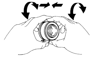 |
Turn the bearing by hand while applying force in the axial direction.
If the bearing sticks or has much resistance, replace the release bearing.
