CLUTCH UNIT > INSTALLATION |
| 1. INSTALL INPUT SHAFT FRONT BEARING |
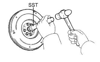 |
Using SST and a hammer, tap in a new bearing.
Install 2 new bolts.
| 2. INSTALL CLUTCH DISC ASSEMBLY |
 |
Insert SST into the clutch disc. Then insert the SST (together with the clutch disc) into the flywheel.
| 3. INSTALL CLUTCH COVER ASSEMBLY |
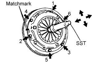 |
Align the matchmarks on the clutch cover and flywheel.
Tighten the 6 bolts as described below.
Determine the first bolt to be tightened by choosing the bolt closest to the knock pin.
Uniformly tighten the 6 bolts in diametrically opposite pairs relative to the position of the first bolt. Use the illustration as a reference.
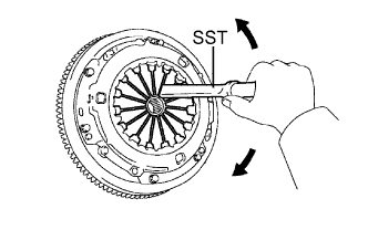
Lightly move SST up and down, and right and left.
Check that the disc is in the center, and then tighten the bolts.
| 4. INSPECT AND ADJUST CLUTCH COVER ASSEMBLY |
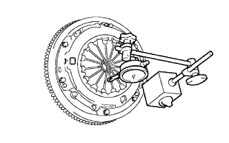 |
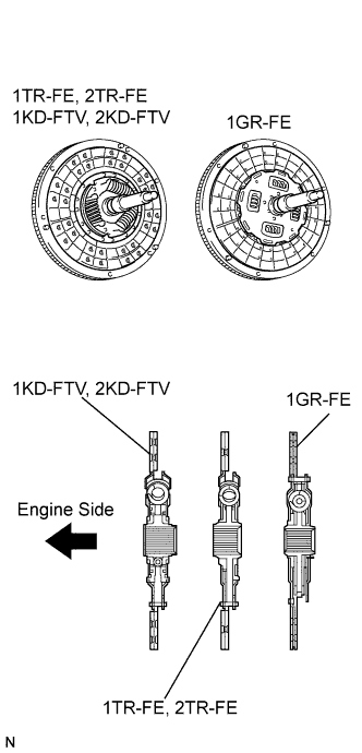
Using a dial indicator with roller instrument, measure the diaphragm spring tip alignment.
 |
| 5. INSTALL RELEASE FORK SUPPORT |
Install the release fork support to the manual transmission unit.
| 6. INSTALL RELEASE BEARING HUB CLIP |
Install the release bearing hub clip to the release bearing.
| 7. INSTALL CLUTCH RELEASE FORK SUB-ASSEMBLY |
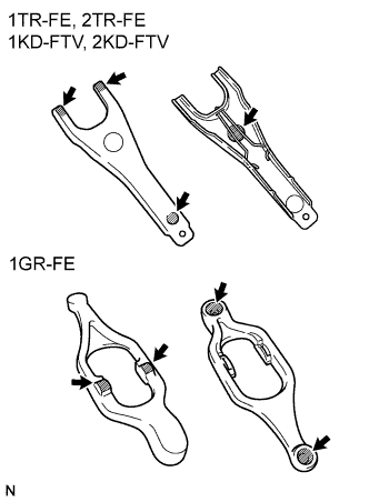 |
Apply release hub grease to the following areas:
Install the release fork to the release bearing.
| 8. INSTALL CLUTCH RELEASE BEARING ASSEMBLY |
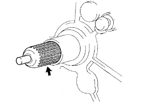 |
Apply clutch spline grease to the input shaft spline.
Install the release fork (with release bearing) to the manual transmission.
| 9. INSTALL CLUTCH RELEASE FORK BOOT |
| 10. INSTALL MANUAL TRANSMISSION UNIT ASSEMBLY |
| 11. INSTALL FRONT PROPELLER SHAFT ASSEMBLY (4WD) |
| 12. INSTALL REAR PROPELLER SHAFT ASSEMBLY |
| 13. INSTALL NO. 1 ENGINE COVER SUB-ASSEMBLY (4WD) |
| 14. INSTALL NO. 2 ENGINE COVER SUB-ASSEMBLY (4WD) |
| 15. CONNECT CABLE TO NEGATIVE BATTERY TERMINAL |
| 16. PERFORM INITIALIZATION |
Perform initialization (Click here ).
| 17. CHECK SRS WARNING LIGHT |
Check the SRS warning light (Click here).
